Advertisements
Fuse Layout Mahindra Thar 2021-2023

Table of Contents
Passenger Compartment Fuse Box
Passenger Compartment Fuse Box
Fuse Box Location
Pull the Fuse box cover below the switch bank, outward to access the instrument panel fuse box.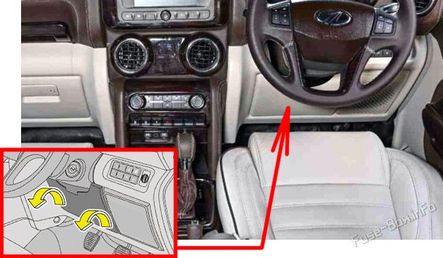
Fuse Box Diagram
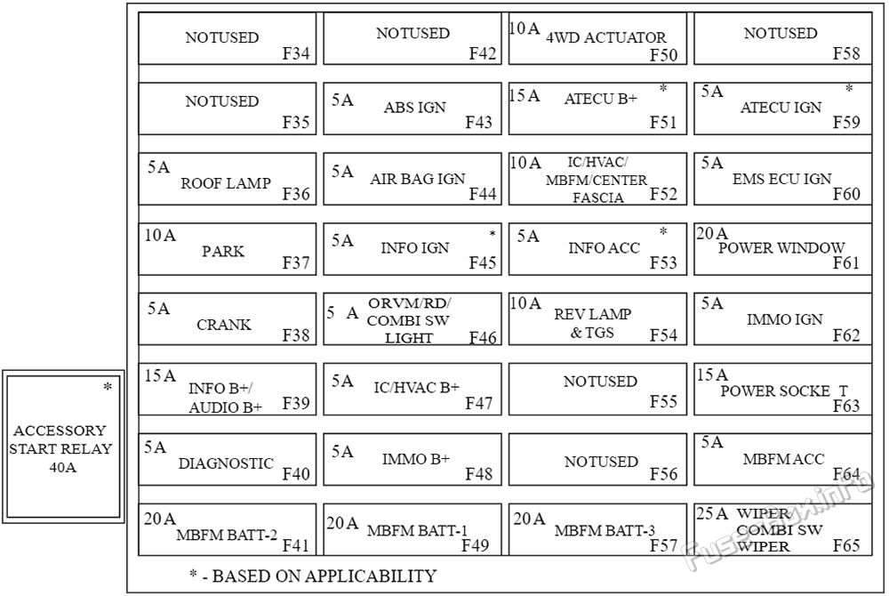
| № | Amps | Circuit |
|---|---|---|
| F34 | – | – |
| F35 | – | – |
| F36 | 5A | ROOF LAMP |
| F37 | 10A | PARK |
| F38 | 5A | CRANK |
| F39 | 15A | INFO B+ / AUDIO B+ |
| F40 | 5A | DIAGNOSTIC |
| F41 | 20A | MBFM BATT-2 |
| F42 | – | – |
| F43 | 5A | ABS IGN |
| F44 | 5A | AIR BAG IGN |
| F45 | 5A | INFO IGN |
| F46 | 5A | ORVM / RD / COMBI SW LIGHT |
| F47 | 5A | IC/HVAC B+ |
| F48 | 5A | IMMO B+ |
| F49 | 20A | MBFM BATT-1 |
| F50 | 10A | 4WD ACTUATOR |
| F51 | 15A | AT ECU B+ |
| F52 | 10A | IC / HVAC / MBFM / CENTER FASCIA |
| F53 | 5A | INFO ACC |
| F54 | 10A | REV LAMP & TGS |
| F55 | – | – |
| F56 | _ | _ |
| F57 | 20A | MBFM BATT-3 |
| F58 | – | – |
| F59 | 5A | AT ECU IGN |
| F60 | 5A | EMS ECU IGN |
| F61 | 20A | POWER WINDOW |
| F62 | 5A | IMMO IGN |
| F63 | 15A | POWER SOCKET |
| F64 | 5A | MBFM ACC |
| F65 | 25A | WIPER / COMBI SW WIPER |
| R1 | 40A | ACCESSORY START RELAY |
Advertisements
Engine Compartment Fuse Box
Engine Compartment Fuse Box
Fuse Box Location
To open the fuse box cover, press the lock and push the cover back and lift it.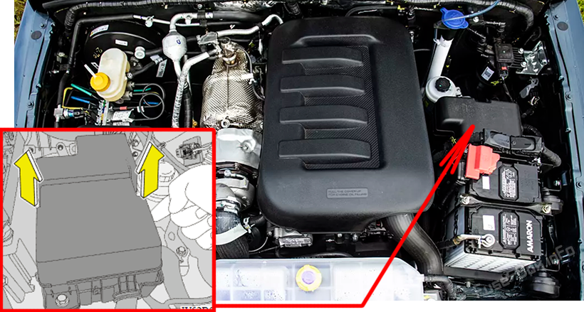
Fuse Box Diagram (Diesel)
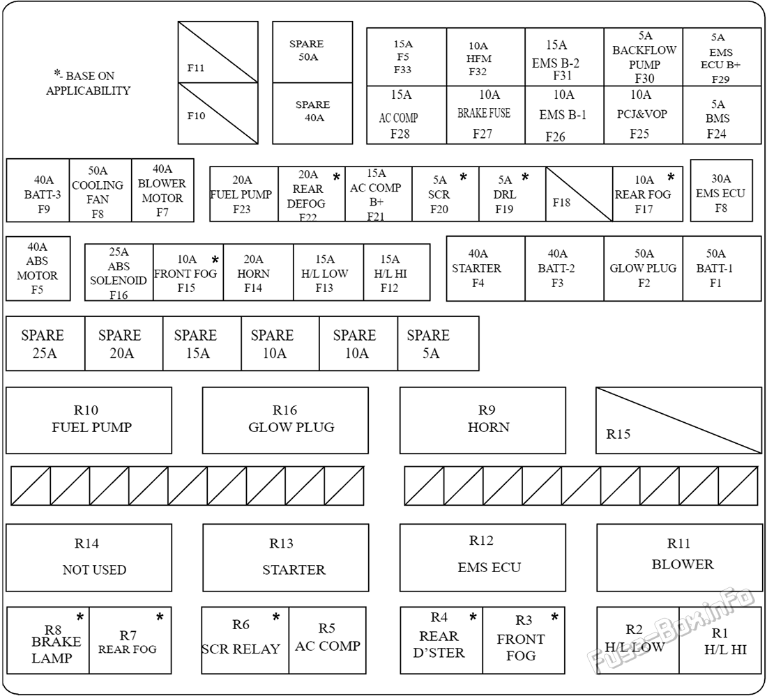
| № | Amps | Circuit |
|---|---|---|
| F1 | 50A | BATT-1 |
| F2 | 50A | GLOW PLUG |
| F3 | 40A | BATT-2 |
| F4 | 40A | STARTER |
| F5 | 40A | ABS MOTOR |
| F6 | 30A | EMS ECU |
| F7 | 40A | BLOWER MOTOR |
| F8 | 50A | COOLING FAN |
| F9 | 40A | BATT-3 |
| F10 | – | – |
| F11 | – | – |
| F12 | 15A | H/L HI |
| F13 | 15 | H/L LOW |
| F14 | 20A | HORN |
| F15 | 10A | FRONT FOG |
| F16 | 25A | ABS SOLENOID |
| F17 | 10A | REAR FOG |
| F18 | – | – |
| F19 | 5A | DRL |
| F20 | 5A | SCR |
| F21 | 15A | AC COMP B+ |
| F22 | 20A | REAR DEFOG |
| F23 | 20A | FUEL PUMP |
| F24 | 5A | BMS |
| F25 | 10A | PCJ&VOP |
| F26 | 10A | EMS B-1 |
| F27 | 10A | BRAKE FUSE |
| F28 | 15A | AC COMP |
| F29 | 5A | EMS ECU B+ |
| F30 | 5A | BACKFLOW PUMP |
| F31 | 15A | EMS B-2 |
| F32 | 10A | HFM |
| F33 | 15A | F5 |
| Relays | ||
| R1 | H/L HI | |
| R2 | H/L LOW | |
| R3 | FRONT FOG | |
| R4 | REAR D’STER | |
| R5 | AC COMP | |
| R6 | SCR RELAY | |
| R7 | REAR FOG | |
| R8 | BRAKE LAMP | |
| R9 | Horn | |
| R10 | FUEL PUMP | |
| R11 | BLOWER | |
| R12 | EMS ECU | |
| R13 | STARTER | |
| R14 | – | |
| R15 | – | |
| R16 | GLOW PLUG |
Fuse Box Diagram (Petrol)
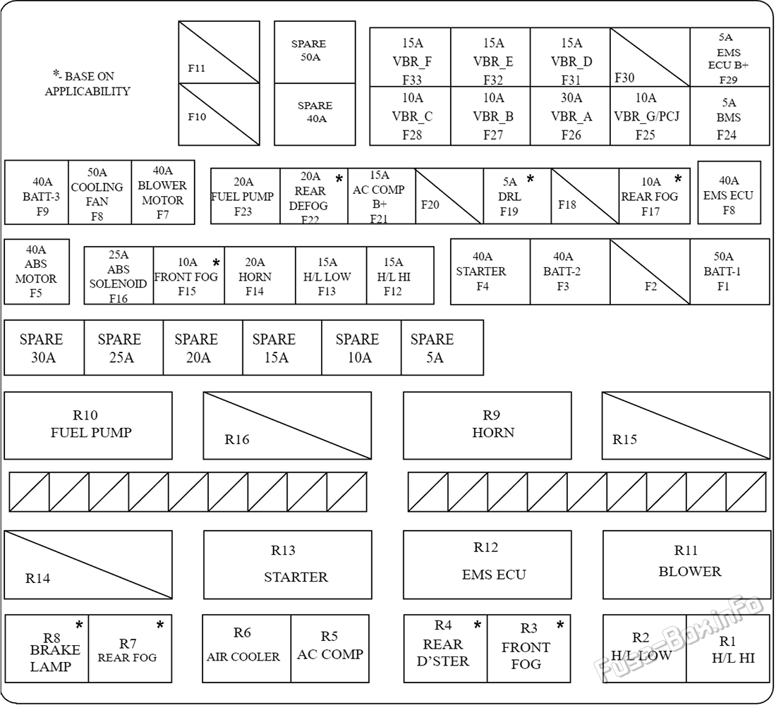
| № | Amps | Circuit |
|---|---|---|
| F1 | 50A | BATT-1 |
| F2 | – | – |
| F3 | 40A | BATT-2 |
| F4 | 40A | STARTER |
| F5 | 40A | ABS MOTOR |
| F6 | 40A | EMS ECU |
| F7 | 40A | BLOWER MOTOR |
| F8 | 50A | COOLING FAN |
| F9 | 40A | BATT-3 |
| F10 | – | – |
| F11 | – | – |
| F12 | 15A | H/L HI |
| F13 | 15A | H/L LOW |
| F14 | 20A | HORN |
| F15 | 10A | FRONT FOG |
| F16 | 25A | ABS SOLENOID |
| F17 | 10A | REAR FOG* |
| F18 | – | – |
| F19 | 5A | DRL |
| F20 | – | – |
| F21 | 15A | AC COMP B+ |
| F22 | 20A | REAR DEFOG |
| F23 | 20A | FUEL PUMP |
| F24 | 5A | BMS |
| F25 | 10A | VBR_G/PCJ |
| F26 | 30A | VBR_A |
| F27 | 10A | VBR_B |
| F28 | 10A | VBR_C |
| F29 | 5A | EMS ECU B+ |
| F30 | – | – |
| F31 | 15A | VBR_D |
| F32 | 15A | VBR_E |
| F33 | 15A | VBR_F |
| Relay | ||
| R1 | H/L HI | |
| R2 | H/L LOW | |
| R3 | FRONT FOG | |
| R4 | REAR D’STER | |
| R5 | AC COMP | |
| R6 | AIR COOLER | |
| R7 | REAR FOG | |
| R8 | BRAKE LAMP | |
| R9 | Horn | |
| R10 | FUEL PUMP | |
| R11 | BLOWER | |
| R12 | EMS ECU | |
| R13 | STARTER | |
| R14 | – | |
| R15 | – | |
| R16 | – |
Battery Mounted Fuse Box
The battery mounted fuse box is connected to the positive terminal of the battery. Functionality of battery mounted fuse box is to provide short circuit protection to alternator and power supply to main engine compartment fuse box.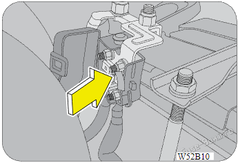
Battery mounted fuse box consist of following fuses:
- Main charging fuse – 150A (Pink colour)
- Bus bar fuse – 80A (White colour)
Advertisements
