Advertisements
Fuse Layout Genesis GV70 2022-2023..
Table of Contents
Fuse Box Location
Fuse Box Location
Passenger Compartment Fuse Box
The fuse panel is located in the driver’s side panel bolster. Open the fuse panel cover to access.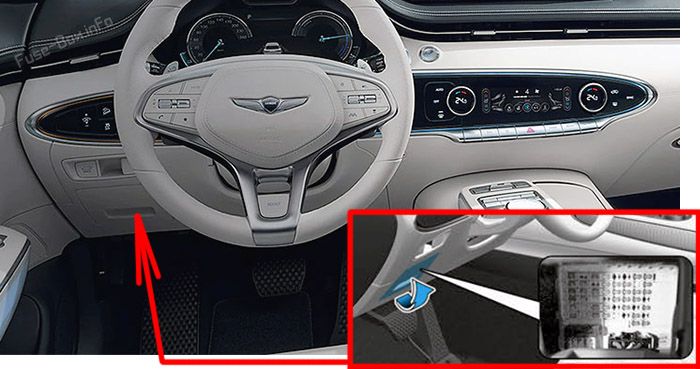
Engine Compartment Fuse Boxes
Remove the fuse panel cover by pressing the tap and pulling up. If the multi fuse or midi fuse is blown, consult an authorized retailer of Genesis Branded products.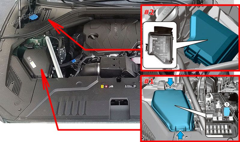
Luggage Compartment Fuse Box
It’s on the left side, behind the cover. 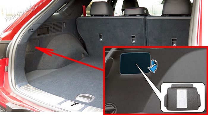
Battery junction block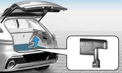
Advertisements
Fuse Box Diagrams
Fuse Box Diagrams
US Version
Passenger Compartment Fuse Box Diagram
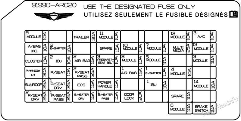
| Fuse Name | Amps | Circuit Protected |
|---|---|---|
| MODULE 9 | 10A | Overhead Console Lamp, AMP, Driver Power Seat Module, Low DC-DC Converter, Electro Chromic Mirror, Data Link Connector, Passenger Power Seat Module, Front A/C Controller, Smart Phone Wireless Charger, Rear A/C Controller, A/V & Navigation Head Unit, A/C Control Module, Fingerprint Recognition Device, Rear Seat Warmer Control Module, Rear Air Ventilation Seat Control Module |
| TRAILER | 30A | Electronic Brake Controller |
| MODULE 11 | 10A | Head Lamp LH/RH, Multifunction Switch, AC Inverter, ADAS Unit (Parking),AC Inverter Outlet, Rear Junction Block (Rear Wiper Relay) |
| MODULE 12 | 10A | IBU, IAU |
| A/C 3 | 10A | E/R SUB Junction Block(PTC Heater 2/3 Relay), A/C Control Module, Incar Temperature Sensor, Rear A/C Controller, Front A/C Controller |
| A/BAG IND | 10A | Instrument Cluster, Overhead Console Lamp |
| E-SHIFTER 2 | 10A | Electronic ATM Shift Lever Dial |
| MODULE 10 | 10A | ICU Junction Block (ESU) |
| MODULE 7 | 10A | Driver Door Module, IBU, IAU, Multifunction Switch, Stop Lamp Switch |
| MULTI MEDIA | 25A | Low DC-DC Converter |
| MODULE 13 | 10A | ICU Junction Block (ESU), Head-Up Display, Security Indicator, A/C Control Module, Front/Rear A/C Controller, Crash Pad Switch, Driver Power Seat Switch, A/V & Navigation Keyboard, Front Console Switch, Fingerprint Recognition Device, Carnish Mood Lamp RH, Mood Lamp Unit, Console Mood Lamp |
| CLUSTER | 10A | Instrument Cluster, Head-Up Display |
| IBU 2 | 10A | IBU |
| AIRBAG2 | 15A | SRS Control Module, Passenger Occupant Detection Sensor |
| PRESAFETY SEAT BELT 3 | 10A | Pre-Active Seat Belt Unit |
| MODULE 8 | 10A | Rear Corner Radar LH/RH, ECS Unit, ELSD Control Module, ADAS Driving ECU, ADAS Parking ECU, Front View Camera, Crash Pad Switch, Steering Tilt & Telescopic Unit |
| MODULE 5 | 10A | Rain Sensor |
| MODULE 3 | 10A | Clock Spring, Steering Tilt & Telescopic Unit, Active Air Flap Module, Multifunction Switch, Rear Occupant Alert (ROA) Sensor |
| P/WINDOW LH | 30A | Driver Power Window Module, Rear Power Window Module LH |
| P/SEAT | 10A | Driver Lumbar Support Unit |
| P/SEAT PASS 2 | 25A | Passenger Power Seat Module, Passenger Power Seat Switch |
| AIRBAG 1 | 15A | SRS Control Module |
| E-SHIFTER 1 | 10A | Electronic ATM Shift Lever Dial |
| MODULE 4 | 10A | Data Link Connector, Passenger Power Seat Switch, Power Liftgate Unit, Driver Power Seat Module, Driver Mood Lamp, Driver Power Seat Switch, Driver Lumbar Support Unit, Passenger Power Seat Module |
| SUNROOF | 25A | Sunroof Control Unit (Master) |
| P/SEAT DRV 1 | 25A | With IMS: Driver Power Seat Module W/O IMS: Driver Power Seat Switch |
| ECS | 15A | ECS Unit |
| POWER HANDLE | 15A | Steering Tilt & Telescopic Unit |
| IBU 1 | 10A | IBU, IAU, BLE Unit, Driver/Passenger Door Outside Handle |
| MODULE 14 | 10A | Front Corner Radar LH/RH, Rear Corner Radar LH/ RH, Head-Up Display, Smart Phone Wireless Charger, Instrument Cluster, Front A/C Controller, Front Console Keyboard, Rear A/C Controller |
| P/SEAT DRV 2 | 25A | With IMS: Driver Power Seat Module W/O IMS: Driver Power Seat Switch |
| P/SEAT PASS 1 | 25A | With Walk In: Passenger Power Seat Module W/O Walk In: Passenger Power Seat Switch |
| S/HEATER DRV | 15A | Driver Power Seat Module |
| S/HEATER PASS 1 | 15A | Passenger Power Seat Module |
| DOOR LOCK | 20A | Center Door Lock Relay, Center Door Unlock Relay, T/ Turn Unlock Relay |
| MODULE 6 | 10A | Armrest Lamp, IBU, IAU, Low DC-DC Converter, Rear USB Charger, Electronic ATM Shift Lever Dial, E/R Sub Junction Block (Power Outlet Relay) |
| BRAKE SWITCH | 10A | Stop Lamp Switch, IBU |
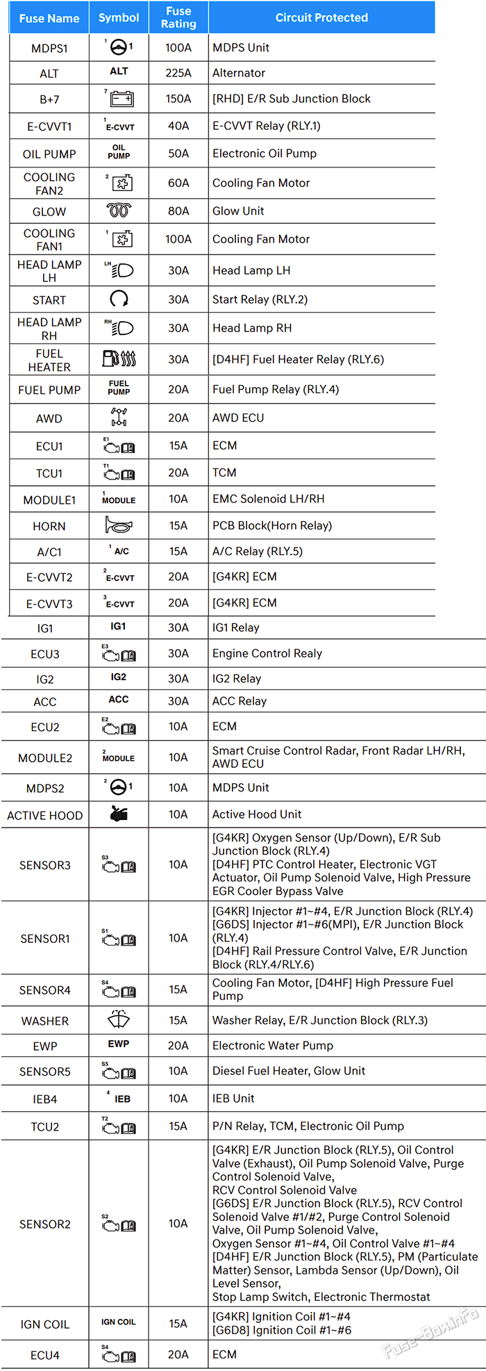
Engine Compartment Fuse Box #1 Diagram
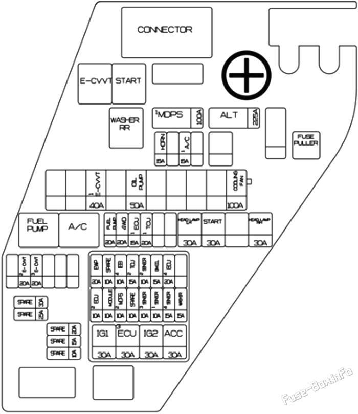
| Fuse Name | Amps | Circuit Protected |
|---|---|---|
| MDPS 1 | 100A | MDPS Unit |
| ALT | 225A | Alternator |
| E-CVVT 1 | 40A | G4KR: E-CWT Relay |
| OIL PUMP | 50A | Electronic Oil Pump |
| COOLING FAN | 100A | Cooling Fan Motor |
| HEAD LAMP LH | 30A | Head Lamp LH |
| START | 30A | Start Relay |
| HEAD LAMP RH | 30A | Head Lamp RH |
| FUEL PUMP | 20A | Fuel Pump Relay |
| 4WD | 20A | AWD ECU |
| ECU 1 | 15A | ECM |
| TCU 1 | 20A | TOM |
| HORN | 15A | PCB Block (Horn Relay) |
| A/C 1 | 15A | A/C Relay |
| E-CVVT 2 | 20A | G4KR: ECM |
| E-CVVT 3 | 20A | G4KR: ECM |
| IG 1 | 30A | IG1 Relay |
| ECU 3 | 30A | Engine Control Realy |
| IG 2 | 30A | IG2 Relay |
| ACC | 30A | ACC Relay |
| ECU 2 | 10A | ECM |
| EWP | 20A | Electronic Water Pump |
| MODULE | 10A | Smart Cruise Control Radar, Front Corner Radar LH/ RH.AWD ECU |
| MDPS 2 | 10A | MDPS Unit |
| IEB 4 | 10A | IEB Unit |
| TCU 2 | 15A | P/N Relay, TCM, Electronic Oil Pump |
| SENSOR 3 | 10A | G4KR: Oxygen Sensor (Up/Down), E/R Sub Junction Block (PTC Heaterl Relay) |
| SENSOR 2 | 10A | G4KR: E/R Junction Block (A/C Relay), Oil Control Valve (Exhaust), Oil Pump Solenoid Valve, Purge Control Solenoid Valve, RCV Control Solenoid Valve, Canister Close Valve G6DS: E/R Junction Block (A/C Relay), RCV Control Solenoid Valve #1/#2, Purge Control Solenoid Valve, Oil Pump Solenoid Valve, Oxygen Sensor #1~#4, Oil Control Valve #1~#4, Canister Close Valve |
| SENSOR 1 | 10A | G4KR: Injector #1~#4, E/R Junction Block (Fuel Pump Relay) G6DS: Injector #1~#6 (MPI), E/R Junction Block (Fuel Pump Relay) |
| IGN COIL | 15A | G4KR: Ignition Coil #1~#4 G6DS: Ignition Coil #1~#6 |
| SENSOR 4 | 15A | Cooling Fan Motor |
| ECU 4 | 20A | ECM |
| WASHER | 15A | Washer Relay, E/R Junction Block (Washer RR Relay) |
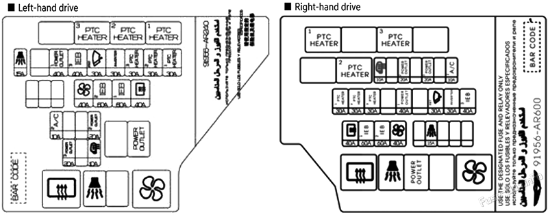
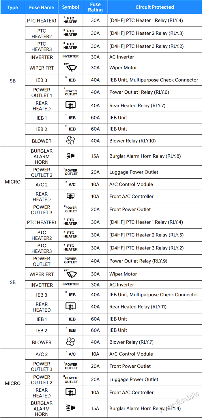
Engine Compartment Fuse Box #2 Diagram
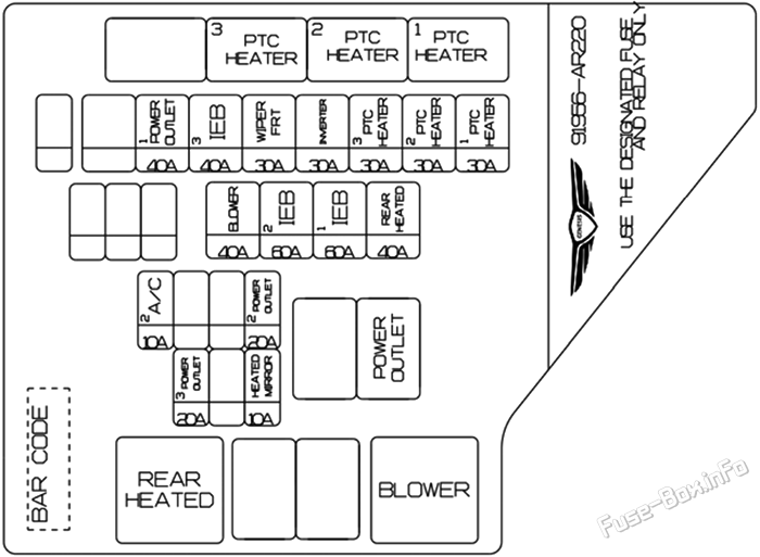
| Fuse Name | Amps | Circuit Protected |
|---|---|---|
| PTC HEATER 1 | 30A | G4KR: PTC Heater 1 Relay |
| PTC HEATER 2 | 30A | G4KR: PTC Heater 2 Relay |
| PTC HEATER 3 | 30A | G4KR: PTC Heater 3 Relay |
| INVERTER | 30A | AC Inverter |
| WIPER FRT | 30A | Wiper Motor |
| IEB 3 | 40A | IEB Unit |
| POWER OUTLET 1 | 40A | Power Outletl Relay |
| REAR HEATED | 40A | Rear Heated Relay |
| IEB 1 | 60A | IEB Unit |
| IEB 2 | 60A | IEB Unit |
| BLOWER | 40A | Blower Relay |
| POWER OUTLET 2 | 20A | Luggage Power Outlet |
| A/C 2 | 10A | A/C Control Module |
| HEATED MIRROR | 10A | Front A/C Controller, Driver/Passenger Power Outside Mirror |
| POWER OUTLET 3 | 20A | Front Power Outlet |
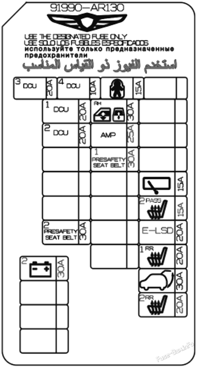
Luggage Compartment Fuse Box Diagram
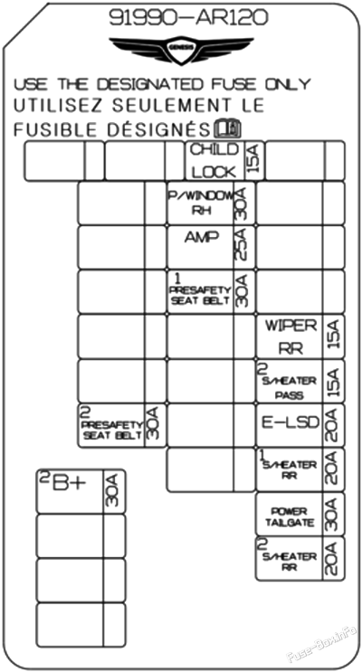
| Fuse Name | Amps | Circuit Protected |
|---|---|---|
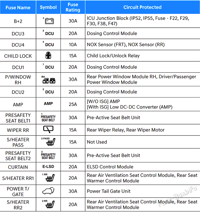
| B+ 2 | 30A | ICU Junction Block (IPS2, IPS5, Fuse - AIR BAG1, E-SHIFTER1, IBU1, MODULE5) |
| CHILD LOCK | 15A | Child Lock/Unlock Relay |
| P/WINDOW RH | 30A | Passenger Power Window Module, Rear Power Window Module RH |
| AMP | 25A | Low DC-DC Converter (AMP) |
| PRESAFETY SEAT BELT 1 | 30A | Pre-Active Seat Belt Unit |
| WIPER RR | 15A | Rear Wiper Relay, Rear Wiper Motor |
| S/HEATER PASS2 | 15A | Not Used |
| PRESAFETY SEAT BELT 2 | 30A | Pre-Active Seat Belt Unit |
| E-LSD | 20A | ELSD Control Module |
| S/HEATER RR 1 | 20A | Rear Air Ventilation Seat Control Module, Rear Seat Warmer Control Module |
| POWER LIFTGATE | 30A | Power Liftgate Unit |
| S/HEATER RR 2 | 20A | Rear Air Ventilation Seat Control Module, Rear Seat Warmer Control Module |
Battery junction block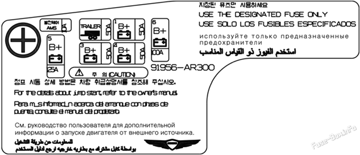
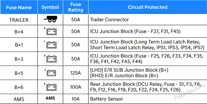
| Fuse Name | Amps | Circuit Protected |
|---|---|---|
| TRAILER | 50A | Trailer Connector |
| B+ 4 | 50A | ICU Junction Block (Fuse - M0DULE4, P/SEAT PASS2, TRAILER, DOOR LOCK) |
| B+ 1 | 50A | ICU Junction Block (Long Term Load Latch Relay, Short Term Load Latch Relay, IPS1, IPS3, IPS4, IPS7) |
| B+ 3 | 50A | ICU Junction Block (Fuse - P/SEAT DRV1, P/SEAT DRV2, S/HEATER DRV, S/HEATER PASS1, P/SEAT PASS1, ECS, P/SEAT, SUNROOF, POWER HANDLE, P/ WINDOW LH) |
| B+ 5 | 125A | E/R SUB Junction Block (B+) |
| B+ 6 | 100A | Rear Junction Block (Fuse - S/HEATER PASS2, S/ HEATER RR1, S/HEATER RR1, P/WNDOW RH, B+2, PRESAFETY SEAT BELT1, PRESAFETY SEAT BELT2) |
| AMS | 10A | Battery Sensor |
Advertisements
UK Version
Passenger Compartment Fuse Box Diagram
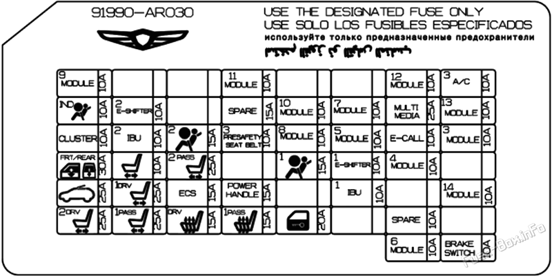

Engine Compartment Fuse Box #1 Diagram
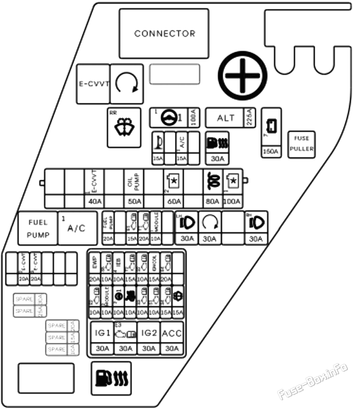
Engine Compartment Fuse Box #2 Diagram
Luggage Compartment Fuse Box Diagram
Battery junction block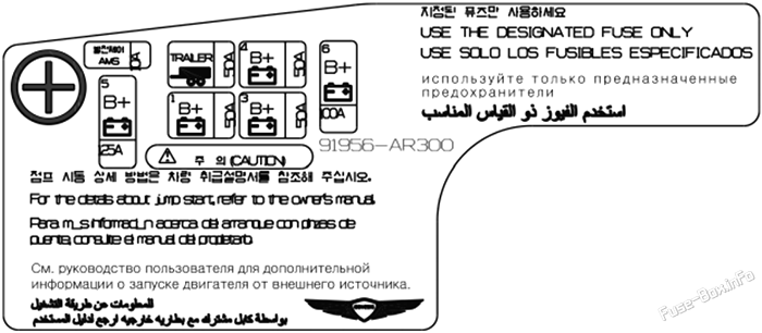
Advertisements

 How to check the fuses?
 How to replace a blown fuse?
 Why do car fuses blow?
 Types of automotive fuses