Advertisements
Fuse Layout VW Taos 2020-2023

Table of Contents
Passenger Compartment Fuse Box (-SC-)
Passenger Compartment Fuse Box (-SC-)
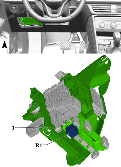
Fuse Box Location
The fuses are behind a cover on the driver’s side. Remove the cover by pulling it to the side in the direction of the arrow.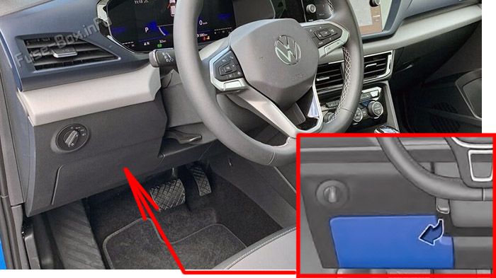
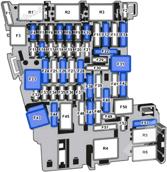
Fuse Box Diagram
| № | Amps | Function / Component |
|---|---|---|
| SC1 | - | - |
| SC2 | 10A | Steering Column Electronics Control Module |
| SC3 | - | - |
| SC4 | - | - |
| SC5 | 7.5A | Data Bus on Board Diagnostic Interface Remote Start System Relay |
| SC6 | 7.5A | Selector lever |
| SC7 | 10A | Heater and A/C Controls Rear Window Defogger Relay A/C Clutch Relay |
| SC8 | 7.5A | Diagnostic Connection Electromechanical Parking Brake Button Humidity, rain and light recognition sensor Rotary Light Switch Parking brake button Instrument Panel Contour Illumination Lamp 1 Instrument Panel Contour Illumination Lamp 2 Anti-Theft Alarm System Sensor Instrument Panel Contour Illumination Lamp 3 Passenger Side Door Ambient Lighting Lamp Driver Side Door Ambient Lighting Lamp |
| SC9 | 7.5A | Steering Column Electronics Control Module |
| SC10 | 7.5A | Front Information Display Control Head |
| SC11 | 40A | Vehicle Electrical System Control Module |
| SC12 | 20A | Information Electronics Control Module 1 Navigation system control module |
| SC13 | - | - |
| SC14 | 40A | Fresh Air Blower Control Module |
| SC15 | - | - |
| SC16 | 7.5A/10A | Storage Compartment with Cell Phone Interface USB Charging Socket 1 (from 2023) USB Connection 1 |
| SC17 | 7.5A | Instrument Cluster Control Module for Emergency Call Module and Communication Unit |
| SC18 | 7.5A | Rear Lid Handle Rearview Camera |
| SC19 | 7.5A | Access/Start System Interface |
| SC20 | 15A | Vacuum Pump Relay |
| SC21 | 15A | All Wheel Drive Control Module |
| SC22 | - | - |
| SC23 | 20A | Sunroof Control Module |
| SC24 | 40A | Vehicle Electrical System Control Module |
| SC25 | 30A | Driver Door Control Module Left rear window regulator motor |
| SC26 | 30A | Vehicle Electrical System Control Module |
| SC27 | 30A | Vehicle Electrical System Control Module |
| SC28 | - | - |
| SC29 | 5A | Refrigerant Circuit Pressure Sensor |
| SC30 | 10A | Remote Start System Relay |
| SC31 | - | - |
| SC32 | 7.5A | Blind Spot Detection Control Module Blind Spot Detection Control Module 2 Parking Aid Control Module Driver Assistance Systems Front Camera Control Module for Adaptive Cruise Control |
| SC33 | 7.5A | Airbag Control Module Front Passenger Airbag "Disabled" Indicator Lamp |
| SC34 | 7.5A | Rotary Light Switch Interior Rearview Mirror Sockets Relay Parking brake button |
| SC35 | 7.5A | Diagnostic Connection |
| SC36 | - | - |
| SC37 | - | - |
| SC38 | - | - |
| SC39 | 30A | Front Passenger Door Control Module Right Rear Window Regulator Motor |
| SC40 | 20A | 12V Socket 12V Socket 2 Sockets Relay |
| SC41 | - | - |
| SC42 | 40A | Vehicle Electrical System Control Module |
| SC43 | 30A | Digitas Sound System Control Module |
| SC44 | - | - |
| SC45 | 15A | Left Front Seat Adjustment Control Head Driver Seat Lumbar Support Adjustment Switch Left Front Seat Cushion Fan 1 Left Front Seat Backrest Fan 1 |
| SC46 | 7.5A | 2020-2022: USB charging socket 1 |
| SC47 | 15A | Rear Window Wiper Motor |
| SC48 | - | - |
| SC49 | 7.5A | Starter Relay 1 Starter Relay 2 Remote Start System Relay |
| SC50 | - | - |
| SC51 | - | - |
| SC52 | - | - |
| SC53 | 30A | Rear Window Defogger Relay |
| R1 | Vacuum Pump Relay | |
| R2 | A/C Clutch Relay | |
| R3 | - | |
| R4 | Terminal 15 Power Supply Relay | |
| R5 | Rear Window Defogger Relay | |
| R6 | Sockets Relay |
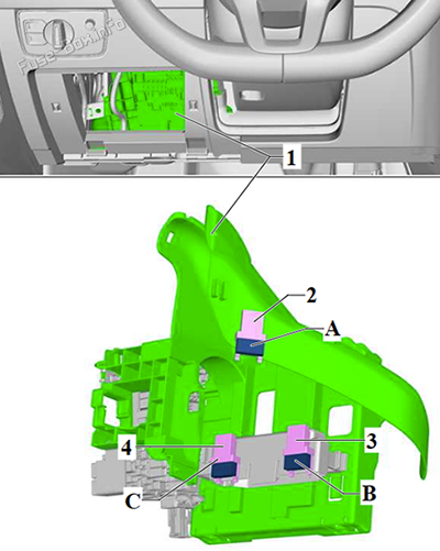
Single fuses
| № | Amps | Function / Component |
|---|---|---|
| A | 15A | Front Passenger Power Seat Adjustment Circuit Breaker 1: Right Front Seat Backrest Fan 1 Right Front Seat Cushion Fan 1 |
| B | - | - |
| C | 7.5A | Seat Belt Latch Release Solenoid Fuse: Passenger Occupant Detection System Control Module |
Remote start system relay
Advertisements
Engine Compartment Fuse Box (-SB-)
Engine Compartment Fuse Box (-SB-)
Fuse Box Location
To unlock the fuse box cover, press the locks in the direction of the arrows. Pull the cover up.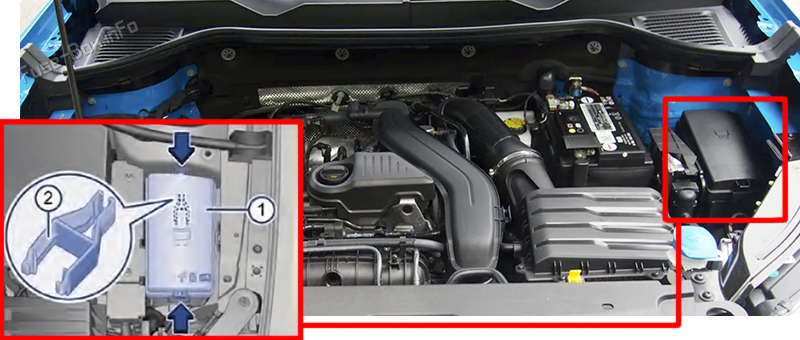
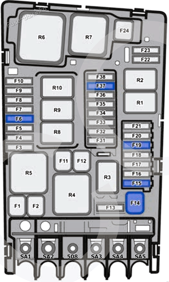
Fuse Box Diagram
| № | Amps | Function / Component |
|---|---|---|
| SA1 | 125A | Supply for Fuses on Fuse Panel C (instrument panel): #4, 12, 14, 32, 35, 39, 40, 42, 49, 52, 53 |
| SA2 | 400A | Generator with Voltage Regulator |
| SA3 | 80A | Power Steering Control Module |
| SA4 | 80A | Supply for Fuses on Fuse Panel C (instrument panel): #2, 15, 19, 21, 23, 27, 30, 43, 45, 51 |
| SA5 | 50A | Radiator Fan |
| SB1 | 25A | ABS Control Module |
| SB2 | 40A/60A | ABS Control Module |
| SB3 | 15A | Engine/Motor Control Module |
| SB4 | 10A | Ethanol concentration sensor Secondary air injection pump relay Radiator Fan Radiator Fan Control Module Radiator Fan Oil Level Thermal Sensor Camshaft Adjustment Valve 1 Intake camshaft adjustment valve 1 Intake Manifold Runner Control Valve EVAP Canister Purge Regulator Valve 1 Oil Pressure Regulation Valve Low Heat Output Relay Vacuum Pump Relay |
| SB5 | - | - |
| SB6 | 7.5A | Brake lamp switch |
| SB7 | 10A | 1.5L gasoline engine: Secondary Air Injection Solenoid Valve Charge air cooling pump Fuel Tank Leak detection Module Tank Switch-Off Valve |
| SB8 | 10A | Oxygen Sensor 1 After Catalytic Converter Heater for Oxygen Sensor 1 After Catalytic Converter Oxygen sensor after catalytic converter Oxygen Sensor 1 Before Catalytic Converter Oxygen Sensor Heater Heated oxygen sensor |
| SB9 | 20A | Ignition Coil 1~4 with Power Output Stage |
| SB10 | 15A | Fuel Pump Control Module |
| SB11 | 40A | Secondary air injection pump motor Secondary air injection pump relay |
| SB12 | - | - |
| SB13 | 30A | Transmission fluid auxiliary hydraulic pump 1 |
| SB14 | 40A | Auxiliary heater heating element Relay and fuse panel 1 |
| SB15 | 15A | Horn Relay |
| SB16 | - | - |
| SB17 | 7.5A | ABS Control Module Engine/Motor Control Module Motronic Engine Control Module Power Supply Relay |
| SB18 | 7.5A | Battery Monitoring Control Module Data Bus on Board Diagnostic Interface |
| SB19 | 30A | Wiper motor relay 1 Wiper motor relay 2 |
| SB20 | - | - |
| SB21 | 15A/30A | Dual-Clutch Transmission Mechatronic Transmission Control Module |
| SB22 | 7.5A | Engine/Motor Control Module |
| SB23 | 30A | Starter |
| SB24 | 30A | Auxiliary heater heating element |
| SB25 | - | - |
| SB26 | - | - |
| SB27 | - | - |
| SB28 | - | - |
| SB29 | - | - |
| SB30 | - | - |
| SB31 | - | - |
| SB32 | 30A/40A | Auxiliary heater heating element |
| SB33 | - | - |
| SB34 | - | - |
| SB35 | - | - |
| SB36 | 15A | Left Front Headlamp |
| SB37 | - | - |
| SB38 | 15A | Right Front Headlamp |
| R1 | Starter Relay 1 | |
| R2 | Starter Relay 2 | |
| R3 | Horn Relay | |
| R4 | Secondary air injection pump relay | |
| R5 | Motronic Engine Control Module Power Supply Relay | |
| R8 | - | |
| R9 | Wiper motor relay 1 | |
| R10 | Wiper motor relay 2 |
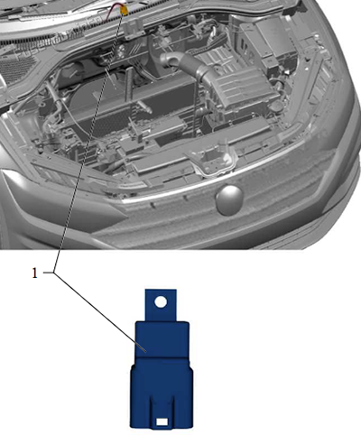
Auxiliary heater relay
Advertisements