Advertisements
See other Jaguar S-Type:
Fuse Layout Jaguar S-Type 1999-2002
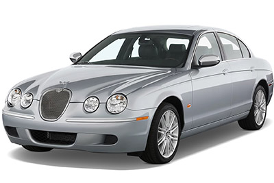
Table of Contents
Passenger Compartment Fuse Box
Fuse Box Location
The passenger compartment fuse box is located on the right-hand side trim panel in the footwell. Remove the fuse box lid by pressing the retaining lugs and lifting.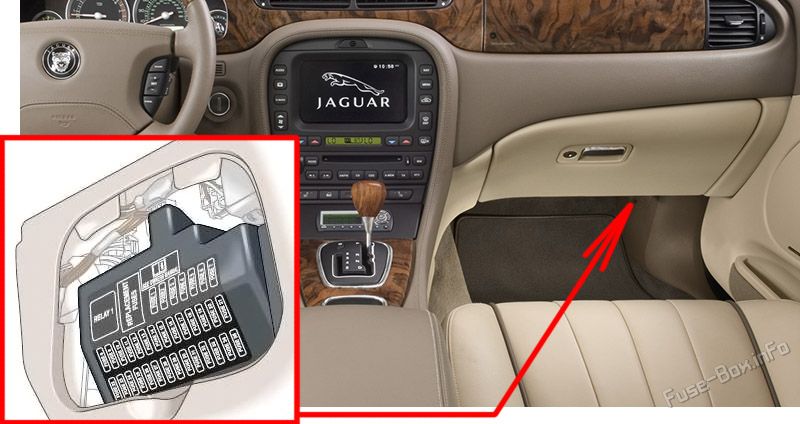
Fuse Box Diagram
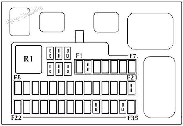
| № | Amps | Circuit |
|---|---|---|
| F1 | 5A | Starter relay coil via Park/Neutral switch |
| F2 | 5A | Radio |
| F3 | 5A | ABS/Dynamic stability control module |
| F4 | 5A | Inertia switch (fuel pump relay, ignition control relay, rear electronics module), instrument cluster. Powertrain Control Module (PCM) relay coil, transit relay |
| F5 | 5A | Autolamp sensor, traction control switch, overdrive cancel switch, heated seat modules, brake shift interlock |
| F6 | 10A | OBD-II connector |
| F7 | 5A | Driver’s Door Module (DDM), Driver’s Seat Module (DSM), Powertrain Control Module (PCM), Passive Anti-Theft System (PATS) LED, security horn, power mirror |
| F8 | 5A | Front right turn indicator, sidemarker, park, repeater lamps |
| F9 | 10A | Right-hand dipped beam, left-hand HID relay coil |
| F10 | 5A | Front left turn indicator, sidemarker, park, repeater lamps |
| F11 | 10A | Left-hand main beam |
| F12 | 10A | Headlamp levelling |
| F13 | 5A | Instrument cluster |
| F14 | 10A | Restraints Control Module (Airbag), Dual Automatic Temperature Control Module |
| F15 | 5A | Adaptive damping module (CATS) |
| F16 | 5A | Heated seat switch module, electrochromic mirror, rain sensor |
| F17 | 5A | Restraints Control Module (Airbag), alternator warning lamp |
| F18 | 20A | Radio, cellular phone, navigation |
| F19 | 15A | Steering column tilt and reach motors |
| F20 | 10A | Generic Electronic Module (GEM), air conditioning, instrument cluster, rear electronic control module |
| F21 | 10A | Power folding mirror, sunblind |
| F22 | 10A | Driver's door module battery supply (driver's door mirror, locks) |
| F23 | 10A | Right-hand main beam |
| F24 | 5A | Passive anti-theft system |
| F25 | 10A | Left-hand dipped beam, right-hand HID relay coil |
| F26 | 10A | - |
| F27 | 10A | Navigation display, radio, phone, navigation module, traffic master |
| F28 | 5A | Security horn |
| F29 | 5A | Voice control, reverse park aid, trailer tow ignition sense, Vehicle Emergency Messaging System (VEMS), Generic Electronic Module (GEM) |
| F30 | 5A | Generic Electronic Module (GEM), passenger power mirror |
| F31 | - | - |
| F32 | 20A | Accessory relay (cigar lighter, power point) |
| F33 | 10A | Generic Electronic Module (GEM) |
| F34 | - | - |
| F35 | 5A | Stop lamp switch |
| R1 | 40A | Accessory relay (cigar lighter, power point) |
Advertisements
Engine Compartment Fuse Box
Fuse Box Location
The fuse box is located in the engine compartment on the right-hand side adjacent to the windscreen wash reservoir. Remove the fuse box lid by pressing the retaining lugs and lifting.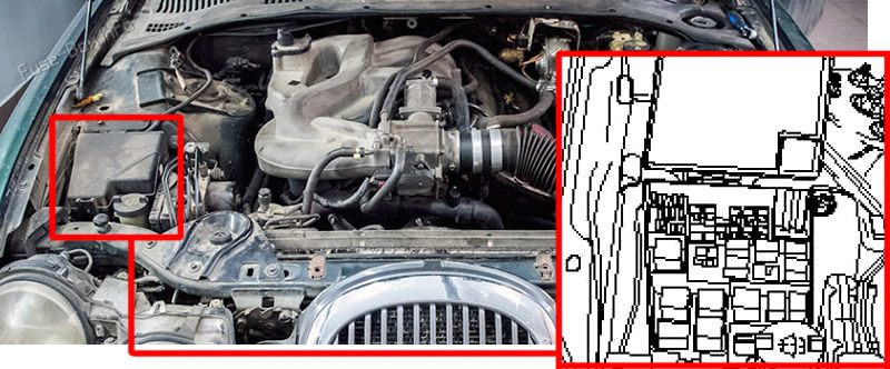
Fuse Box Diagram
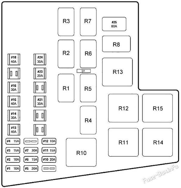
| № | Amps | Circuit |
|---|---|---|
| 1 | 10A | Air conditioning clutch (auxiliary water pump - V8 engine only) |
| 2 | 10A | Windshield washer pump |
| 3 | 15A | Fog lamps, LH/RH |
| 4 | 15A | Horns |
| 5 | 20A | Fuel injection |
| 6 | 15A | Transmission solenoid |
| 7 | - | - |
| 8 | - | - |
| 9 | - | - |
| 10 | - | - |
| 11 | 15A | Heated oxygen sensors, air conditioning clutch coil relay |
| 12 | 10A | Coil on plugs |
| 13 | 40A | LH heated windshield |
| 14 | 30A | ABS module |
| 15 | 40A | RH heated windshield or Heated wiper park |
| 16 | 30A | Blower motor |
| 17 | - | - |
| 18 | 40A | Powertrain Control Module (PCM) |
| 19 | - | - |
| 20 | - | - |
| 21 | 30A | Starter solenoid |
| 22 | 30A | ABS motor |
| 23 | 20A | Wiper motor |
| 24 | 30A | Headlamp washer pump |
| 25 | 80A | Cooling fan motor |
| D1 | - | Powertrain control diode |
| Relay | ||
| R1 | Wiper high/low relay | |
| R2 | Wiper park relay | |
| R3 | Powertrain control relay 2 | |
| R4 | Throttle control relay | |
| R5 | Auxiliary coolant pump relay (v8) | |
| R6 | Horn relay | |
| R7 | Front fog lamp relay | |
| R8 | A/C compressor clutch relay | |
| R10 | Blower motor relay | |
| R11 | Wiper park heater relay / RH windshield heater relay | |
| R12 | LH windshield heater relay | |
| R13 | Powerwash relay | |
| R14 | Powertrain control relay 1 | |
| R15 | Starter relay |
Advertisements
Luggage Compartment Fuse Box
Fuse Box Location
A fuse box is located in the luggage compartment, situated forward of the battery. Fold the luggage compartment floor panel to gain access to the fuse box. Remove the fuse box lid by pulling the retaining clips and pulling the lid upwards.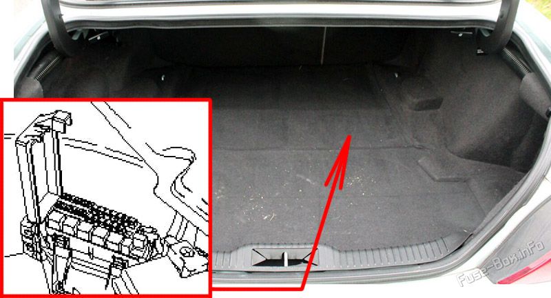
Fuse Box Diagram
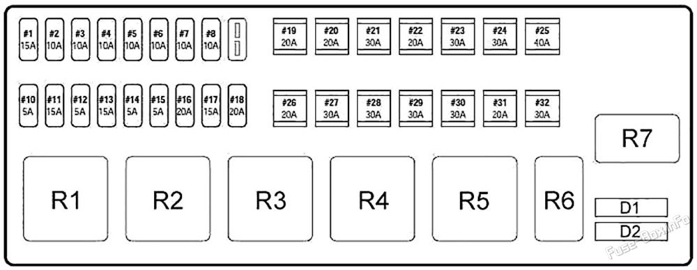
| № | Amps | Circuit |
|---|---|---|
| 1 | 15A | Luggage compartment lid release |
| 2 | 10A | Right rear - reverse lamp, direction indicator, side markers, fog lamps, licence plate |
| 3 | 10A | Left stop lamp, tail lamp, trailer tow relay |
| 4 | 10A | Fuel flap release, trunk lamp |
| 5 | 10A | Courtesy and map lamps |
| 6 | 10A | Left rear - reverse lamp, direction indicator, side markers, fog lamps |
| 7 | 10A | Right stop lamp, tail lamp |
| 8 | 10A | High mounted stop light |
| 9 | 5A | Heated mirror |
| 10 | 5A | Traffic master |
| 11 | 15A | Seat heaters |
| 12 | 5A | Transit relay |
| 13 | 15A | Adaptive damping module |
| 14 | 5A | Cellular phone, CD changer, Vehicle Emergency Messaging System (VEMS) |
| 15 | 5A | Alternator Sensor |
| 16 | 20A | Sunroof |
| 17 | 15A | Fuel pump |
| 18 | 20A | Subwoofer amplifier |
| 19 | 20A | Rear Electronic Module (REM) - left rear window |
| 20 | 30A | Driver’s door module (DDM) - driver’s window |
| 21 | 30A | Driver’s lumbar |
| 22 | 20A | Ignition |
| 23 | 30A | Switched system power 4 |
| 24 | 30A | Switched system power 3 |
| 25 | 40A | Primary Junction Box (PJB) |
| 26 | 20A | Generic Electronic Module (GEM) - passenger window |
| 27 | 30A | Switched system power 1 |
| 28 | 30A | Passenger’s lumbar |
| 29 | 30A | Rear screen defrost |
| 30 | 20A | Rear Electronic Module (REM) - right rear window |
| 31 | 20A | Ignition |
| 32 | 30A | Switched system power 2 |
| D1 | Not used | |
| D2 | Fuel pump diode | |
| Relay | ||
| R1 | Switched system power relay 1 | |
| R2 | Switched system power relay 2 | |
| R3 | Heated backlight relay | |
| R4 | Switched system power relay 3 | |
| R5 | Switched system power relay 4 | |
| R6 | Gearshift interlock relay | |
| R7 | Fuel pump relay |
Advertisements


 How to check the fuses?
 How to replace a blown fuse?
 Why do car fuses blow?
 Types of automotive fuses