Advertisements
Fuse Layout GAC GN6 / GM6
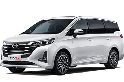
Table of Contents
Passenger Compartment Fuse Box
Passenger Compartment Fuse Box
Fuse Box Location
Open and withdraw the storage box on lower guard plate of the driving cab in direction of the arrow.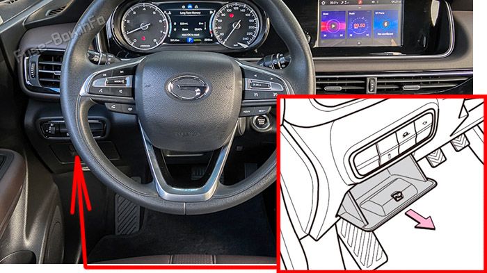
Fuse Box Diagram
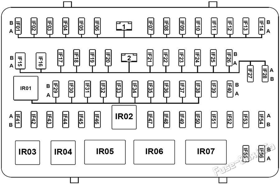
| № | Amps | Function / Component |
|---|---|---|
| IF01 | — | — |
| IF02 | 20A | Electric seat adjustment |
| IF03 | 20A | Power sunroof control unit / panorama sunroof control unit / panorama sunroof sunshade motor |
| IF04 | — | — |
| IF05 | 20A | Body control module (front right window regulator) |
| IF06 | 20A | Body control module (front left window regulator) |
| IF07 | 20A | Body control module (rear right window regulator) |
| IF08 | 20A | Body control module (rear left window regulator) |
| IF09 | 7.5A | Smartphone wireless charging module |
| IF10 | — | — |
| IF11 | 15A | Body control module (windshield washer and rear wiper motor) |
| IF12 | 10A | Rear-view mirror folding |
| IF13 | — | — |
| IF14 | — | — |
| IF15 | — | — |
| IF16 | 30A | Instrument panel fuse box |
| IF17 | 7.5A | OBD Diagnosis Interface |
| IF18 | 20A | Body control module (main light) |
| IF19 | 7.5A | Gateway module |
| IF20 | 7.5A | Gearshift module |
| IF21 | 10A | Body control module (turn signal) |
| IF22 | — | — |
| IF23 | 7.5A | PEPS control unit / Ignition switch / ESCL |
| IF24 | 20A | Body control module (main light) |
| IF25 | 7.5A | High brake light / EPB switch |
| IF26 | 20A | Body control module (door lock) |
| IF27 | — | — |
| IF28 | SHUNT | Divider |
| IF29 | 10A | SRS control unit |
| IF30 | 7.5A | Engine control unit / AT control unit |
| IF31 | 7.5A | Gateway module/ body control module / PEPS control unit |
| IF32 | — | — |
| IF33 | 7.5A | Steering angular speed sensor / EPS control unit/gearshift module |
| IF34 | 7.5A | Brake switch / ESP and EPB control module |
| IF35 | 7.5A | Parking sensor control unit / panoramic parking control unit /rear A/C control panel / seat heating |
| IF36 | 7.5A | Air quality sensor/anion generator |
| IF37 | 7.5A | Front left combination light (height adjustment motor) / front right combination light (height adjustment motor) / headlight height adjustment switch / automatic headlight control unit |
| IF38 | 7.5A | Rain and light sensor / power sunroof control unit / panoramic sunroof control unit / front A/C control panel / A/C control unit / instrument cluster / AUDIO control unit |
| IF39 | 15A | AT control unit |
| IF40 | 15A | AUDIO control unit |
| IF41 | 7.5A | Body control module / PEPS control unit |
| IF42 | 7.5A | USB charging port 1 / USB charging port 2 |
| IF43 | 25A | Right trunk 12V power supply interface |
| IF44 | 7.5A | AUDIO control unit / rear-view mirror adjustment switch |
| IF45 | 25A | Front 12V power supply interface |
| IF46 | — | — |
| IF47 | 7.5A | Front blower relay / rear blower relay / defogging relay / PEPS control unit / electric anti-glare interior rear-view mirror |
| IF48 | — | — |
| IF49 | — | — |
| IF50 | 7.5A | Body control module / PEPS control unit / engine control unit / starter relay 1 / starter relay 2 |
| IF51 | 7.5A | Panoramic parking control unit |
| IF52 | 7.5A | Automatic headlight control unit |
| IF53 | 7.5A | Front left door handle switch |
| IF54 | 7.5A | A/C control unit / PM2.5 sensor |
| IF55 | 15A | Body Control Module |
| IF56 | 7.5A | Front A/C control panel / rear A/C control panel / AUDIO display / instrument cluster |
| IR01 | — | IG1 relay |
| IR02 | — | IG2 relay |
| IR03 | — | — |
| IR04 | — | — |
| IR05 | — | ACC relay |
| IR06 | — | Rear-view mirror folding relay |
| IR07 | — | Rear-view mirror unfolding relay |
Advertisements
Engine Compartment Fuse Box
Engine Compartment Fuse Box
Fuse Box Location
Press the fixing clip in direction of the arrow and release the fuse box cover.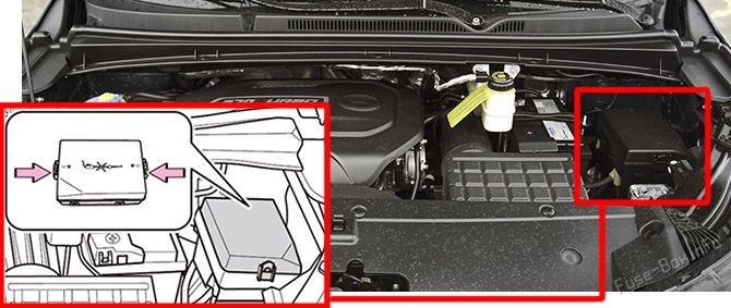
Fuse Box Diagram
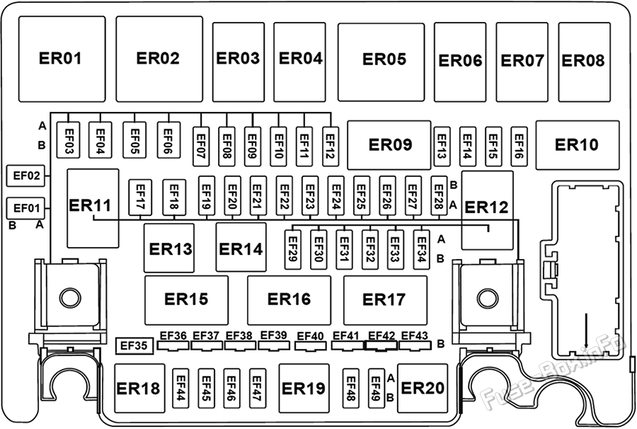
| № | Amps | Function / Component |
|---|---|---|
| EF01 | — | — |
| EF02 | — | — |
| EF03 | 40A | Rear Blower |
| EF04 | 40A/60A | ESP and EPB control module |
| EF05 | — | — |
| EF06 | — | — |
| EF07 | 7.5A | A/C compressor |
| EF08 | — | — |
| EF09 | — | — |
| EF10 | 20A | Seat Heating |
| EF11 | 20A | High beam relay (high beam) |
| EF12 | — | — |
| EF13 | 15A | Front Left Low Beam |
| EF14 | 15A | Front Right Low Beam |
| EF15 | 7.5A | Engine control unit |
| EF16 | 7.5A | Left rear-view mirror defogger / right rear-view mirror defogger |
| EF17 | — | — |
| EF18 | 40A | ACC relay / ignition switch / IG1 relay |
| EF19 | 7.5A | Low Beam Relay |
| EF20 | — | — |
| EF21 | — | — |
| EF22 | — | — |
| EF23 | 20A | Fuel pump |
| EF24 | 25A | Wiper |
| EF25 | 7.5A | Brake switch / main relay / starter relay 1 / starter relay 2 / engine control unit / ESP and EPB control module |
| EF26 | 15A | Horn relay / horn |
| EF27 | — | — |
| EF28 | — | — |
| EF29 | — | — |
| EF30 | 10A | Variable cam timing (intake end) / variable cam timing (exhaust end) / discharge valve / throttle valve / carbon canister solenoid valve / oil pump solenoid valve |
| EF31 | 10A | Compressor relay/front oxygen sensor/rear oxygen sensor |
| EF32 | 15A | Engine control unit / clutch position sensor / starter relay 1 |
| EF33 | 15A | Ignition coil 1 / ignition coil 2 / ignition coil 3 / ignition coil 4 |
| EF34 | 10A | Electronic fan relay / fuel pump relay |
| EF35 | 80A | EPS control unit |
| EF36 | 40A | Instrument panel fuse box |
| EF37 | 40A | Front Blower |
| EF38 | 40A | ESP and EPB control module |
| EF39 | 40A | Rear-view mirror defogger / rear windshield defogger |
| EF40 | 150 A | Divider |
| EF41 | 30A | Starter relay 1 / starter relay 2 / ignition switch / IG2 relay |
| EF42 | — | — |
| EF43 | 50A | Instrument panel fuse box |
| EF44 | — | — |
| EF45 | — | — |
| EF46 | — | — |
| EF47 | — | — |
| EF48 | — | — |
| EF49 | — | — |
| ER01 | — | Front Blower Relay |
| ER02 | — | Rear Blower Relay |
| ER03 | — | Fuel pump relay |
| ER04 | — | — |
| ER05 | — | Electronic fan relay |
| ER06 | — | Wiper speed regulation relay |
| ER07 | — | Wiper relay |
| ER08 | — | High Beam Relay |
| ER09 | — | Defogging relay |
| ER10 | — | — |
| ER11 | — | Low Beam Relay |
| ER12 | — | Main Relay |
| ER13 | — | Compressor Relay |
| ER14 | — | — |
| ER15 | — | Starter relay 1 |
| ER16 | — | Starter Relay 2 |
| ER17 | — | — |
| ER18 | — | — |
| ER19 | — | Horn Relay |
| ER20 | — | — |
Advertisements

 How to check the fuses?
 How to replace a blown fuse?
 Why do car fuses blow?
 Types of automotive fuses