Advertisements
Fuse Layout Holden Vectra 2002-2005
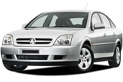
Table of Contents
Passenger Compartment Fuse Box
Passenger Compartment Fuse Box
Fuse Box Location
To remove the cover, pull firmly on the handle and lift out. A fuse gripping tool is supplied in the fuse box cover to aid in fuse removal. Spare fuses can be stored in this fuse box cover.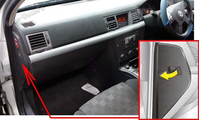
Fuse Box Diagram
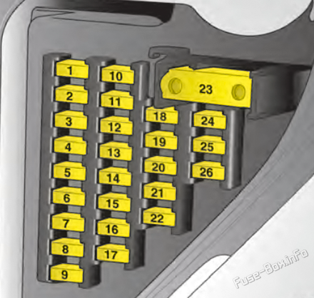
| № | Amps | Function |
|---|---|---|
| 1 | 20A | Radio |
| 2 | 7.5A | Interior fan, heating, air conditioning |
| 3 | 20A | Sun roof |
| 4 | — | — |
| 5 | 7.5A | Door module control unit |
| 6 | 7.5A | Brake light |
| 7 | 30A | Bodywork module control unit |
| 8 | 30A | Control unit Front passenger door module |
| 9 | 7.5A | Central control unit |
| 10 | 7.5A | Control unit Steering column module |
| 11 | 5A | Diagnostics plug |
| 12 | 15A | Battery overload protection |
| 13 | — | — |
| 14 | — | — |
| 15 | 30A | Control unit Driver's door module |
| 16 | — | — |
| 17 | 15A | Instruments, information display |
| 18 | 7.5A | Air conditioning system |
| 19 | — | — |
| 20 | 7.5A | Yaw sensor (ESP, if fitted) |
| 21 | — | — |
| 22 | 30A | Cigarette lighter (if fitted) |
| 23 | 40A | Interior fan, air conditioning system, climate control |
| 24 | — | — |
| 25 | 7.5A | Heating, air conditioning |
| 26 | 7.5A | Instruments, information display |
Advertisements
Engine Compartment Fuse Box
Engine Compartment Fuse Box
Fuse Box Location
To remove the fuse box cover, first remove the battery cover; pull it forward and upwards. To remove the fuse box cover, push the latch and lift as illustrated.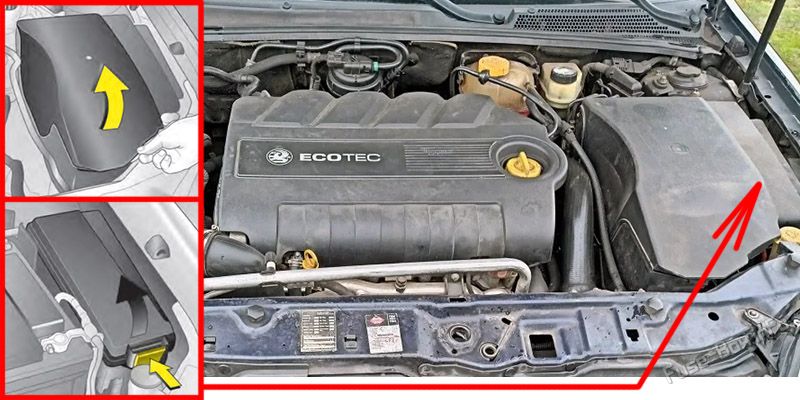
Fuse Box Diagram
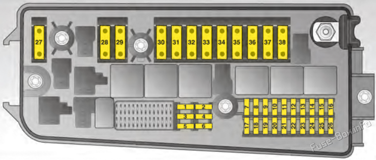
| № | Amps | Function |
|---|---|---|
| 1 | 20A | Engine electronics, transmission electronics |
| 2 | 25A | Starter motor |
| 3 | 20A | Horn |
| 4 | 10A | Air conditioning, climate control |
| 5 | 15A | Windscreen washer system |
| 6 | — | — |
| 7 | 15A | Central control unit, traction control, Electronic Stability Program |
| 8 | 10A | Headlights |
| 9 | — | — |
| 10 | — | — |
| 11 | 30A | Windscreen wiper |
| 12 | 30A | Windscreen wiper |
| 13 | 7.5A | Central control unit, traction control, ESP (if fitted) |
| 14 | — | — |
| 15 | 10A | Exhaust gas sensors |
| 16 | 7.5A | ABS |
| 17 | — | — |
| 18 | — | — |
| 19 | 5A | Headlight range adjustment |
| 20 | — | — |
| 21 | — | — |
| 22 | — | — |
| 23 | 20A | Auxiliary heating |
| 24 | 30A | Battery voltage, terminal 30 |
| 25 | 30A | Battery voltage, terminal 30 |
| 26 | — | — |
| 27 | — | — |
| 28 | 60A | Tailgate module control unit |
| 29 | 40A | ABS |
| 30 | 60A | Tailgate module control unit |
| 31 | 60A | Vehicle interior module control unit |
| 32 | 40A | ABS |
| 33 | 60A | Vehicle interior module control unit |
| 34 | 60A | Tailgate module control unit |
| 35 | 20A | Cooling fan |
| 36 | 30A | Cooling fan |
| 37 | — | — |
| 38 | — | — |
Advertisements
Luggage Compartment Fuse Box
Luggage Compartment Fuse Box
Fuse Box Location
To remove the cover, push the bar down and open the cover.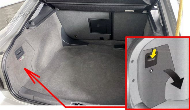
Fuse Box Diagram
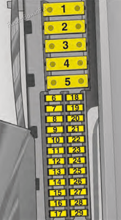
| № | Amps | Function |
|---|---|---|
| 1 | — | — |
| 2 | — | — |
| 3 | — | — |
| 4 | 40A | Rear demister |
| 5 | — | — |
| 6 | 30A | Electric windows |
| 7 | 30A | Electric windows |
| 8 | — | — |
| 9 | 15A | Horn |
| 10 | 20A | Fuel pump |
| 11 | 25A | Battery voltage, terminal 30 |
| 12 | — | — |
| 13 | 20A | Towing equipment |
| 14 | 15A | Rear window wiper |
| 15 | — | — |
| 16 | — | — |
| 17 | — | — |
| 18 | — | — |
| 19 | 7.5A | Tank flap |
| 20 | — | — |
| 21 | — | — |
| 22 | — | — |
| 23 | — | — |
| 24 | 25A | Battery voltage, terminal 30 |
| 25 | — | — |
| 26 | — | — |
| 27 | 5A | Air conditioning |
| 28 | — | — |
| 29 | — | — |
Advertisements

 How to check the fuses?
 How to replace a blown fuse?
 Why do car fuses blow?
 Types of automotive fuses