Advertisements
Fuse Layout Ford Expedition 2022->
Table of Contents
Passenger Compartment Fuse Box
Passenger Compartment Fuse Box
Fuse Box Location
The Body Control Module Fuse Box is in the right-hand side of the passenger footwell behind a trim panel.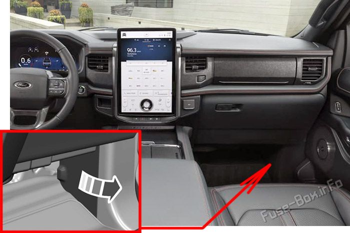
Fuse Box Diagram
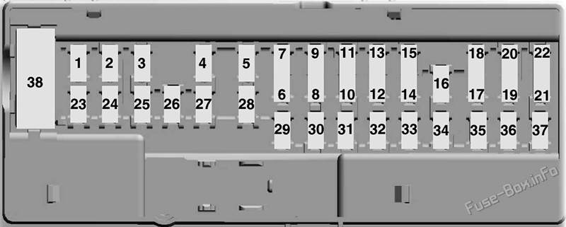
| № | Amp. | Protected Component |
|---|---|---|
| 1 | - | Not used. |
| 2 | 10 A | Driver seat switch. |
| 3 | 7.5 A | Driver door unlock. |
| 4 | 20 A | Speaker amplifier. |
| 5 | - | Not used. |
| 6 | 10 A | Smart datalink connector logic. |
| 7 | 10 A | Rear audio control module. |
| 8 | 5 A | Wireless accessory charger. Hands-free liftgate module. |
| 9 | 5 A | Keypad. Combined sensor module. |
| 10 | - | Not used. |
| 11 | - | Not used. |
| 12 | 7.5 A | Instrument cluster. |
| 13 | 7.5 A | Steering column control module. Smart datalink connector logic. Climate control module. Gearshift module. |
| 14 | 15 A | Brake switch. |
| 15 | 15 A | SYNC. |
| 16 | - | Not used. |
| 17 | - | Not used. |
| 18 | 7.5 A | Gearshift module. Column shifter. |
| 19 | 5 A | Telematics control unit module. |
| 20 | 5 A | Ignition switch. |
| 21 | 5 A | In-vehicle temperature and humidity sensor. |
| 22 | 5 A | Electrochromic mirror. Second row heated seat module. |
| 23 | 30 A | Power window switch. Power mirror switch. Left-hand front door zone module. |
| 24 | 30 A | Moonroof logic. |
| 25 | 20 A | Speaker amplifier 2. |
| 26 | 30 A | Right-hand front door zone module. |
| 27 | 30 A | Left-hand rear door zone module. |
| 28 | 30 A | Right-hand rear door zone module. |
| 29 | 15 A | Adjustable pedals. |
| 30 | 5 A | Trailer tow control module. |
| 31 | 10 A | Rear climate control module. Drive mode switch module. Terrain management switch. Radio frequency transceiver module. 4x4 switch. |
| 32 | 20 A | Audio control module. |
| 33 | - | Not used. |
| 34 | 30 A | Run/start relay. |
| 35 | 5 A | Not used (spare). |
| 36 | 15 A | Image processing module A. Automated park assist module. Continuous control clamping module. |
| 37 | 20 A | Heated steering wheel. |
| 38 | 30A CB | Left-hand rear power window. Right-hand rear power window. |
Advertisements
Engine Compartment Fuse Box
Engine Compartment Fuse Box
Fuse Box Location
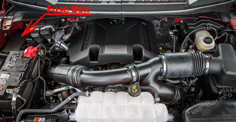
Fuse Box Diagram
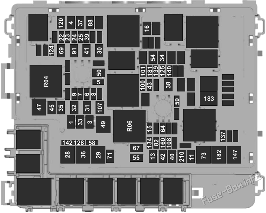
| № | Amp. | Protected Component |
|---|---|---|
| 1 | 30 A | Body control module 1. |
| 3 | 30 A | Body control module 2. |
| 4 | 30 A | Fuel pump. |
| 5 | 5 A | Powertrain control module relay. |
| 6 | 20 A | Vehicle power 1. |
| 7 | 25 A | Vehicle power 2. |
| 8 | 20 A | Vehicle power 3. |
| 9 | 20 A | Vehicle power 4. |
| 11 | 30 A | Starter relay. |
| 13 | 40 A | Front blower motor. |
| 15 | 20 A | Horn. |
| 16 | 20 A | Windshield washer pump. |
| 22 | 10 A | Electronic power assist steering run/start feed. |
| 23 | 10 A | Anti-lock brake system run/ start feed. |
| 24 | 10 A | Powertrain control module. Transmission control module. |
| 25 | 10 A | Rear view camera. Air quality sensor run/start feed. |
| 28 | 50 A | Anti-lock brake system pump. |
| 29 | 50 A | Anti-lock brake system valves. |
| 30 | 30 A | Driver seat motors. |
| 31 | 30 A | Passenger seat motors. |
| 32 | 20 A | Power point 1. |
| 33 | 20 A | Power point 2. |
| 34 | 20 A | Power point 3. |
| 35 | 20 A | Power point 4. |
| 36 | 40 A | Inverter. |
| 37 | 30 A | Climate controlled seats (passenger side). |
| 38 | 30 A | Climate controlled seats (driver side). |
| 39 | 20 A | Second row seat module. |
| 40 | 40 A | Power running boards. |
| 41 | 30 A | Powered liftgate module. |
| 42 | 30 A | Trailer brake control module. |
| 43 | 5 A | Not used (spare). |
| 45 | 20 A | Power point 5. |
| 47 | 50 A | Electric fan 1. |
| 49 | 50 A | Electric fan 2. |
| 50 | 40 A | Heated rear window. |
| 54 | 40 A | Electronic limited slip differential. |
| 55 | 30 A | Trailer tow parking lamps relay. |
| 58 | 10 A | Trailer tow backup lamps. |
| 59 | 20 A | Not used (spare). |
| 64 | 25 A | Four-wheel drive module 1. |
| 67 | 15 A | Transmission run/start. |
| 69 | 30 A | Left-hand side wiper motor. |
| 71 | 20 A | Rear window wiper relay. |
| 73 | 50 A | Power folding seat module - third row. |
| 82 | 25 A | Four-wheel drive module 2. |
| 88 | 40 A | Auxiliary blower. |
| 91 | 20 A | Trailer tow lighting module power. |
| 100 | 25 A | Left-hand headlamp. |
| 101 | 25 A | Right-hand headlamp. |
| 107 | 30 A | Trailer battery charge. |
| 108 | 20 A | Spot lamps (police). |
| 120 | 15 A | Fuel injectors. |
| 124 | 5 A | Rain sensor module. |
| 125 | 5 A | USB smart charger 1. |
| 128 | 7.5 A | Family entertainment system. |
| 134 | 20 A | Multi-contour seats relay. |
| 137 | 20 A | Advanced driver-assistance systems module. Connected camera. |
| 139 | 5 A | USB smart charger 2. |
| 140 | 5 A | USB smart charger 3. |
| 142 | 5 A | USB smart charger 5. |
| 147 | 40 A | Intercooler puller fan relay. |
| 160 | 10 A | Smart data link connector. |
| 181 | 5 A | Not used (spare). |
| 182 | 60 A | Driver door control module. |
| 183 | 60 A | Passenger door control module. |
| 210 | 30 A | Body control module start stop. |
| R04 | Electric fan 1 relay. | |
| R06 | Electric fan 3 relay. |
Advertisements


 How to check the fuses?
 How to replace a blown fuse?
 Why do car fuses blow?
 Types of automotive fuses