Advertisements
Fuse Layout Genesis G70 2021-2023..
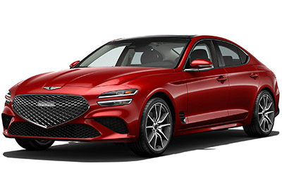
Table of Contents
Fuse Box Location
Fuse Box Location
Passenger Compartment Fuse Box
The fuse panel is located in the driver’s side panel bolster. Open the fuse panel cover to access.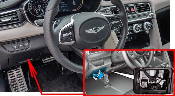
Engine Compartment Fuse Box
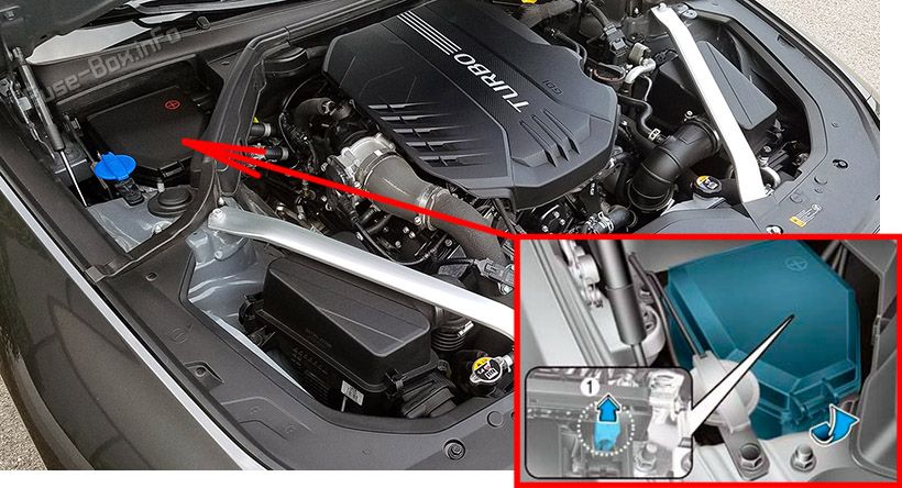
Trunk Fuse Box
The fuse box is on the right side, behind the panel. Battery junction block is under the floor cover.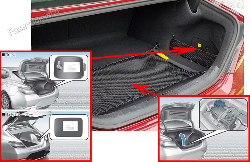
Advertisements
Fuse Box Diagrams
Fuse Box Diagrams
US Version
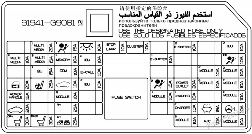
Passenger Compartment Fuse Box Diagram
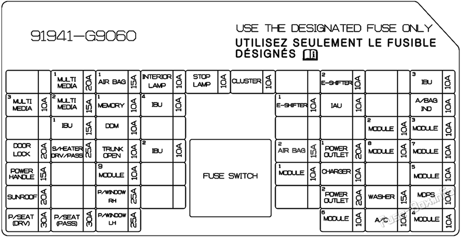
| Fuse Name | Amps | Circuit Protected |
|---|---|---|
| MULTI MEDIA 1 | 20A | W/O ISG: Fuse - F11, F12 With ISG: Low DC-DC Converter (Audio) |
| AIRBAG 1 | 15A | SRS Control Module |
| ROOM LAMP | 10A | Overhead Console Lamp, Center Room Lamp, Room Lamp Vanity Lamp Switch LH/RH, Luggage Lamp LH/ RH Glove Box Lamp, Driver/Passenger Foot Lamp |
| STOP LAMP | 10A | IBU, Stop Lamp Switch |
| CLUSTER | 10A | Instrument Cluster, Head-Up Display |
| E-SHIFTER 2 | 10A | Electronic ATM Shift Lever |
| IBU 3 | 10A | IBU |
| MULTI MEDIA 3 | 10A | With ISG: Instrument Cluster, Head-Up Display, A/C Switch Front Wireless Charger, Surround View Monitor ECU W/O ISG: Surround View Monitor ECU, Rear Corner Radar LH/RH |
| MULTI MEDIA 2 | 15A | Audio |
| MEMORY 1 | 10A | A/C Control Module, A/C Switch, Security Indicator Head-Up Display, Power Tail Gate Unit, Power Trunk Module W/O ISG: Instrument Cluster |
| IBU 4 | 10A | IBU |
| E-SHIFTER 1 | 10A | Electronic ATM Shift Lever |
| AIRBAG IND. | 10A | Instrument Cluster, Overhead Console Lamp |
| IBU 1 | 15A | IBU, Driver/Passenger Smart Key Outside Handle, Driver/Passenger Power Outside Mirror |
| DRIVER DR MODULE | 10A | Driver Door Module, Driver/Passenger Power Outside Mirror |
| E-CALL | 10A | Emergency Call Module |
| MODULE 2 | 10A | IBU |
| MODULE 3 | 10A | Driver Door Module, Stop Lamp Switch |
| DOOR LOCK | 20A | Door Lock Relay, Door Unlock Relay, Dead Lock Relay |
| SEAT HEATER | 25A | Front Air Ventilation Seat Control Module Front Seat Warmer Control Module |
| TRUNK | 10A | Trunk Lid Relay, Fuel Lid Relay, Crash Pad Switch |
| IBU 2 | 10A | IBU, Rain Sensor |
| AIRBAG 2 | 15A | SRS Control Module |
| POWER OUTLET 1 | 20A | Front Power Outlet |
| MODULE 8 | 10A | Cooling Fan Controller (BLDC Motor) |
| MODULE 7 | 10A | Dosing Control Module, AWD ECM, Active Air Flap LH, ECS Unit, Front View Camera, Console Switch, Crash Pad Switch, IBU, Console Switch, Front View Camera, Front Wireless Charger, Steering Tilt & Telescopic Module, Surround View Monitor ECU, Electronic Control Engine Mounting Module, Steering Angle Sensor |
| POWER HANDLE | 15A | Steering Tilt & Telescopic Module |
| MODULE 9 | 10A | Driver Air Lumbar Control Unit |
| MODULE 1 | 10A | Data Link Connector, Console Switch, Hazard Switch,Electronic Control Engine Mounting Module |
| CHARGER | 10A | Front/Rear USB Charger, Front Tray USB Charger |
| MODULE 5 | 10A | A/C Control Module, A/C Switch, A/V & Navigation Head Unit, Low DC-DC Converter (Audio/AMP), Electro Chromic Mirror, AMP, Emergency Module, Driver IMS Control Module, Front Air Ventilation Seat Control Module, Data Link Connector, Front/Rear Seat Warmer Control Module, IFS Module |
| SUNROOF | 20A | Sunroof Control Unit (Glass) |
| PASSENGER P/ WINDOW | 25A | Passenger Safety Power Window Module, Rear Power Window Switch RH, Rear Safety Power Window Module RH |
| POWER OUTLET 2 | 20A | 5DR: Rear Power Outlet |
| WASHER | 15A | Multifunction Switch |
| MDPS | 10A | MDPS Unit |
| DRIVER P/SEAT | 30A | Driver IMS Control Module, Driver Seat Manual Switch |
| PASSENGER P/SEAT | 30A | Passenger Seat Manual Switch, Passenger Walk In Relay Module |
| DRIVER P/WINDOW | 25A | Driver Safety Power Window Module, Rear Safety Power Window Module LH, Rear Power Window Switch LH |
| MODULE 6 | 10A | Surround View Monitor ECU, IBU, Emergency Call Module, AMP, Electronic ATM Shift Lever, Overhead Console Lamp, A/V & Navigation Head Unit, Low DC-DC Converter (Audio/AMP) |
| A/CON | 10A | A/C Control Module, A/C Switch, PM Sensor (A/C), E/R Junction Block (RLY.6), Diesel Junction Block (RLY.3/4) |
| MODULE 4 | 10A | Head Lamp LH/RH, Auto Head Lamp Leveling Device Module |
Engine Compartment Fuse Box Diagram
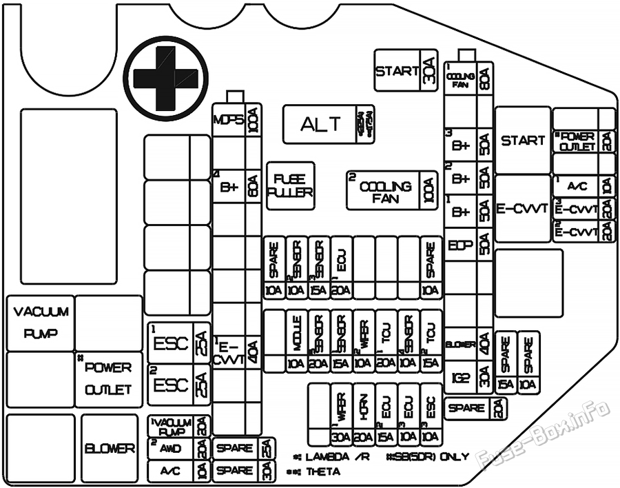
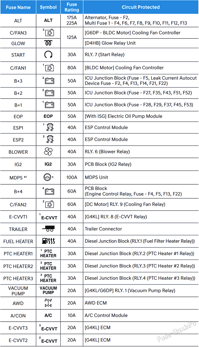
| Fuse Name | Amps | Circuit Protected |
|---|---|---|
| ALT | 175A / 225A | Alternator, Fuse - F2, Multi Fuse 1 - F4, F6, F7, F8, F9, F10, F11, F12, F13 |
| C/FAN 3 | 125A | G6DP - BLDC Motor: Cooling Fan Controller |
| GLOW | 125A | D4HB: Glow Relay Unit |
| START | 30A | RLY. 7 (Start Relay) |
| C/FAN 1 | 80A | BLDC Motor: Cooling Fan Controller |
| B+ 3 | 50A | ICU Junction Block (Fuse - F5, Leak Current Autocut Device Fuse - F2, F4, F13, F14, F21, F22) |
| B+ 2 | 50A | ICU Junction Block (Fuse - F27, F35, F43, F51, F52) |
| B+ 1 | 50A | ICU Junction Block (Fuse - F28, F29, F37, F45, F53) |
| EOP | 50A | With ISG: Electric Oil Pump Module |
| ESP 1 | 40A | ESP Control Module |
| ESP 2 | 40A | ESP Control Module |
| BLOWER | 40A | RLY. 6 (Blower Relay) |
| IG2 | 30A | PCB Block (IG2 Relay) |
| MDPS | 100A | MDPS Unit |
| B+ 4 | 60A | PCB Block (Engine Control Relay, Fuse - F4, F5, F13, F22) |
| C/FAN 2 | 60A | DC Motor: RLY. 9 (Cooling Fan Relay) |
| E-CVVT 1 | 40A | G4KL: RLY. 8 (E-CVVT Relay) |
| TRAILER | 40A | Trailer Connector |
| VACUUM PUMP | 20A | G4KL/G6DP: RLY. 1 (Vacuum Pump Relay) |
| AWD | 20A | AWD ECM |
| A/CON | 10A | A/C Control Module |
| E-CVVT 3 | 20A | G4KL: ECM |
| E-CVVT 2 | 20A | G4KL: ECM |
| ESC 3 | 10A | ESP Control Module |
| ECU 3 | 10A | ECM |
| ECU 2 | 15A | ECM |
| HORN | 20A | Horn Relay |
| WIPER 1 | 30A | Wiper Power Relay |
| TCU 2 | 15A | P/N Relay, TCM |
| SENSOR 4 | 10A | Electronic Oil Pump Module, Brake Vacuum Switch, E/R Junction Block (RLY.1 (Brake Vacuum Relay)) |
| TCU 1 | 20A | TCM |
| WIPER 2 | 10A | IBU, ECM |
| SENSOR 1 | 15A | Rear Sub Junction Block (Fuel Pump Relay), D4HB: Rail Pressure Regulating Valve, DieseL Junction Block (RLY.1 (Fuel Filter Heater Relay)) |
| SENSOR 5 | 20A | G4KL: Ignition Coil #1/#2/#3/#4 G6DP: Ignition Coil #1/#2/#3/#4/#5/#6 D4HB: Electronic Water Pump |
| MODULE | 10A | Active Air Flap LH |
| SENSOR 1 | 10A | D4HB: Glow Relay Unit, Fuel Heater & Water Separator Sensor |
| ECU 1 | 20A | ECM |
| SENSOR 3 | 15A | G4KL: Oxygen Sensor (Up/Down) G6DP: Oxygen Sensor #1/#2/#3/#4 D4HB: Lambda Sensor #1/#2, Electronic VGT Actuator, Fuel Metering Unit, EGR Cooing Bypass Solenoid Vlave, PTC Heater, Mid Nox Sensor, PM Sensor, Rear Nox Sensor |
| SENSOR 2 | 10A | E/R Junction Block (RLY. 9 - Cooling Fan Relay), G4KL: Electronic Thermostat, Oil Control Valve, Purge Control Solenoid Valve, Recirculation Control Solenoid Valve G6DP: Electronic Thermostat, Oil Pressure Solenoid Valve, Oil Control Valve #1/#2/#3/#4 (Intake/ Exhaust), Recirculation Control Solenoid Valve, Purge Control Solenoid Valve, Variable Exhaust Flap Actuator LFH/RFH D4FHB: Oil Pump Solenoid Valve, Air Flow Sensor, Crankshaft Position Sensor, Front Nox Sensor, Oil Level Sensor, Stop Lamp Switch |
| B/ALARM | 10A | E/R Junction Block (RLY. 2 - Burglar Alarm Horn Relay) |
| Relay | ||
| RLY. 1 | Vacuum OIK090033 | |
| RLY. 2 | Burglar Alarm Horn Relay | |
| RLY. 6 | Blower Relay | |
| RLY. 7 | Start Relay | |
| RLY. 8 | E-CVVT Relay (G4KL) | |
| RLY. 9 | Cooling Fan Relay |
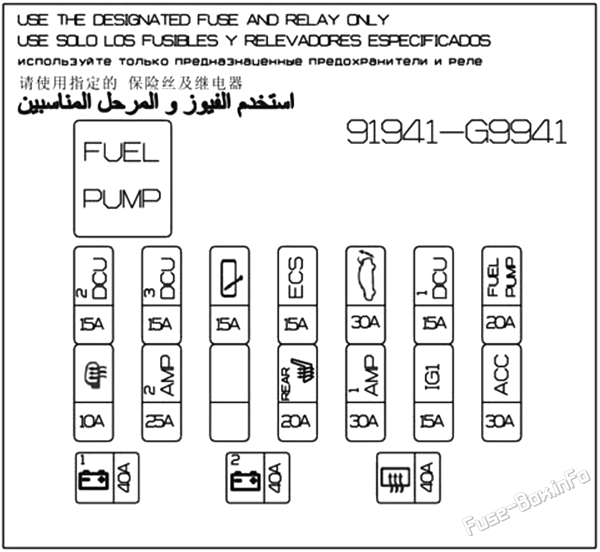
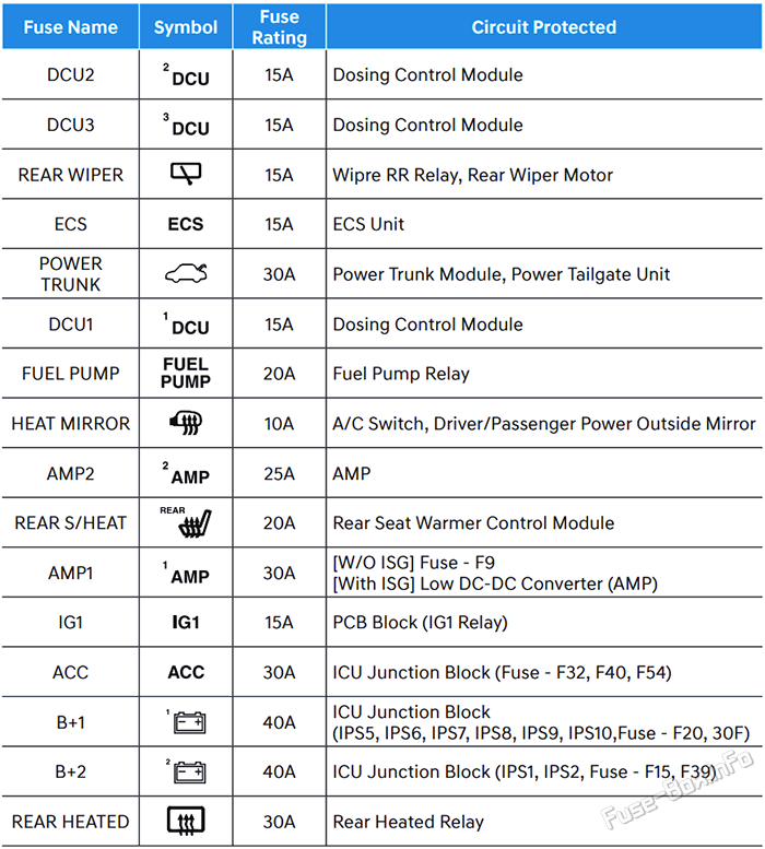
Trunk Fuse Box Diagram
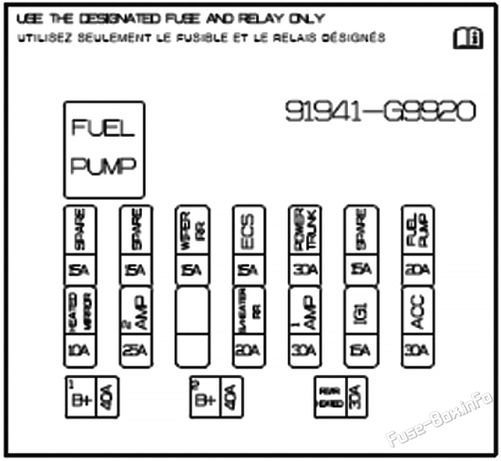
| Fuse Name | Amps | Circuit Protected |
|---|---|---|
| DCU 2 | 15A | Dosing Control Module |
| DCU 3 | 15A | Dosing Control Module |
| REAR WIPER | 15A | Wipre RR Relay, Rear Wiper Motor |
| ECS | 15A | ECS Unit |
| POWER TRUNK | 30A | Power Trunk Module, Power Tailgate Unit |
| DCU 1 | 15A | Dosing Control Module |
| FUEL PUMP | 20A | Fuel Pump Relay |
| HEAT MIRROR | 10A | A/C Switch, Driver/Passenger Power Outside Mirror |
| AMP 2 | 25A | AMP |
| REAR S/HEAT | 20A | Rear Seat Warmer Control Module |
| AMP 1 | 30A | W/O ISG: Fuse - F9 With ISG: Low DC-DC Converter (AMP) |
| IG1 | 15A | PCB Block (IG1 Relay) |
| ACC | 30A | ICU Junction Block (Fuse - F32, F40, F54) |
| B+ 1 | 40A | ICU Junction Block (IPS5, IPS6, IPS7, IPS8, IPS9, IPS10, Fuse - F20, 30F) |
| B+ 2 | 40A | ICU Junction Block (IPS1, IPS2, Fuse - F15, F39) |
| REAR HEATED | 30A | Rear Heated Relay |
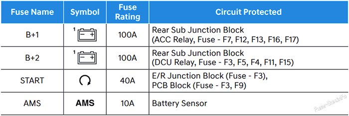
Battery junction block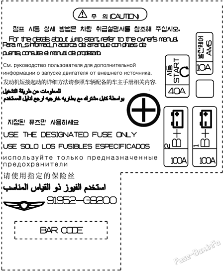
| Fuse Name | Amps | Circuit Protected |
|---|---|---|
| B+ 1 | 100A | Rear Sub Junction Block (ACC Relay, Fuse - F7, F12, F13, F16, F17) |
| B+ 2 | 100A | Rear Sub Junction Block (DCU Relay, Fuse - F3, F5, F4, F11, F15) |
| START | 40A | E/R Junction Block (Fuse - F3), PCB Block (Fuse - F3, F9) |
| AMS | 10A | Battery Sensor |
Advertisements
UK Version
Passenger Compartment Fuse Box Diagram

Engine Compartment Fuse Box Diagram
Left-hand drive vehicles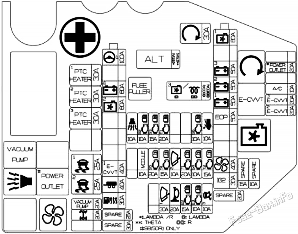
Right-hand drive vehicles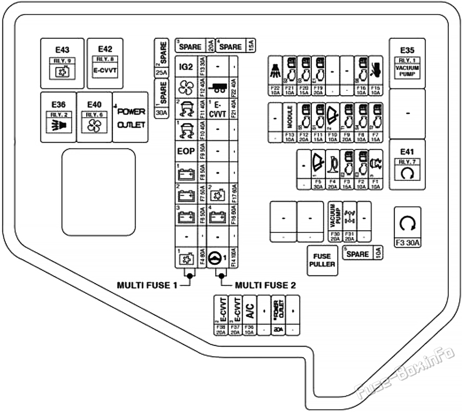

Trunk Fuse Box Diagram
Battery junction block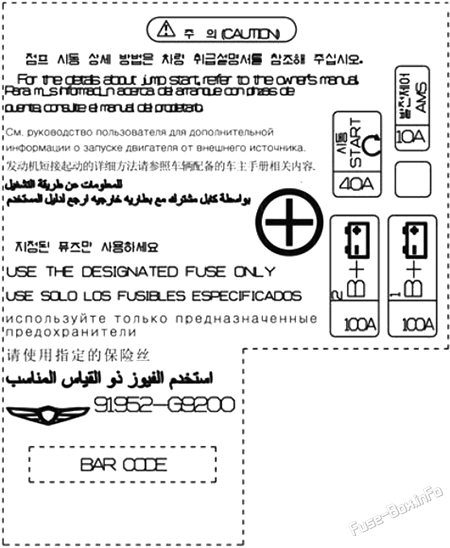
Advertisements

 How to check the fuses?
 How to replace a blown fuse?
 Why do car fuses blow?
 Types of automotive fuses