
Advertisements


Fuse Layout Holden Captiva 5 (2011-2016)

Table of Contents
Passenger Compartment Fuse Box
Passenger Compartment Fuse Box
Fuse Box Location
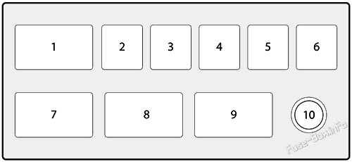
The fuses are located in the floor console on the driver side. To open the fuse cover, pull the latch rearwards to disengage the cover.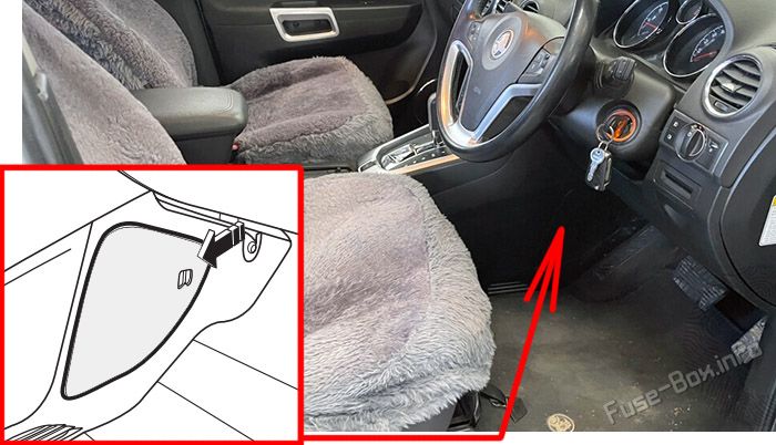
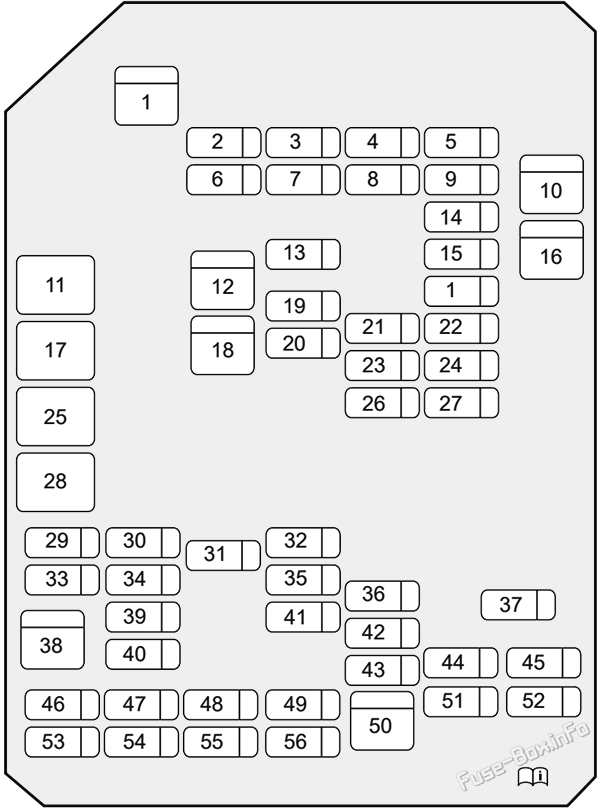
Fuse Box Diagram
| № | Amps | Description |
|---|---|---|
| 1 | 30A | DRVR PWR SEAT |
| 2 | 10A | S/ROOF FOLDING MIRROR |
| 3 | 20A | FSCM / VENT SOL |
| 4 | 15A | F/DOOR LOCK |
| 5 | 20A | DR/LCK |
| 6 | 20A | TRLR |
| 7 | 20A | APO JACK (CONSOLE) |
| 8 | 20A | HTD SEAT PWR / REAR A/C |
| 9 | 15A | BCM (PRK/TRN) |
| 10 | 30A | PASS PWR WNDW |
| 11 | ACC/RAP RELAY | |
| 12 | 20A | 2011-2013: S/ROOF BATT |
| 13 | 20A | CIGAR |
| 14 | 15A | BCM (STOP) |
| 15 | 15A | BCM (CTSY) |
| 16 | 20A | DRV PWR WNDW |
| 17 | CIGAR / APO JACK RELAY | |
| 18 | 20A | 2014-2016: S/ROOF BATT |
| 19 | 20A | APO JACK REAR CARGO |
| 20 | 15A | RUN/CRANK |
| 21 | SPARE | |
| 22 | 30A | AMP |
| 23 | 15A | BCM (TRN SIG) |
| 24 | 15A | DRL |
| 25 | RUN RELAY | |
| 26 | 20A | FRT WSR |
| 27 | 10A | L/GATE |
| 28 | RUN/CRANK RELAY | |
| 29 | 20A | HEATING MAT SW |
| 30 | 10A | FSCM |
| 31 | 15A | AWD/VENT |
| 32 | 15A | 2015-2016: RR HEAT SEAT |
| 33 | 10A | RUN2 |
| 34 | 5A | ISRVM/RCM |
| 35 | 15A | RR FOG |
| 36 | 15A | BCM (DIMMER) |
| 37 | 15A | LOGISTIC MODE |
| 38 | 40A | HVAC BLWR |
| 39 | 10A | CLSTR |
| 40 | 10A | SDM (IGN 1) |
| 41 | 5A | PWR DIODE |
| 42 | 10A | 2011-2014: XBCM 2015-2016: BCM (VBATT) |
| 43 | 30A | TRLR BATT |
| 44 | 15A | RVS / HVAC / DLC |
| 45 | 2A | PWR / MODING |
| 46 | 10A | SSPS |
| 47 | 10A | XBCM |
| 48 | 20A | BCM (INT LIGHT) / TRLR FOG |
| 49 | 10A | IPC |
| 50 | 30A | 2015-2016: DC DC CONVERTER |
| 51 | 10A | SDM (BATT) |
| 52 | SPARE | |
| 53 | 2A | OSRVM |
| 54 | 10A | AUDIO / KEY CAPTURE |
| 55 | SPARE | |
| 56 | 2A | STR/WHL SW |
Advertisements
Engine Compartment Fuse Box
Engine Compartment Fuse Box
Fuse Box Location
This fuse box is located toward the rear of the engine compartment next to the coolant reservoir, it contains circuit fuses, main fuses and relays. To remove the cover, press the catch on the side of the fuse box toward the engine and release the two tabs at the opposite side.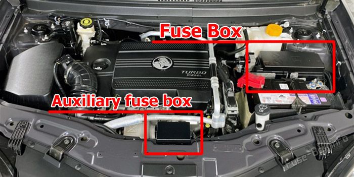
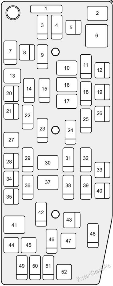
Fuse Box Diagram
| № | Amps | Description |
|---|---|---|
| 1 | 80A | PWM FAN |
| 2 | 2011-2013: FAN1 RELAY | |
| 3 | 15A | 2011-2014: IGNITION COIL A 2015-2016: COIL A - OIL PUMP |
| 4 | 15A | IGNITION COIL B |
| 5 | 40A | 2011-2013: FAN1 |
| 6 | 2011-2013: FAN2 RELAY | |
| 7 | 15A | ECM |
| 8 | 40A | 2011-2013: FAN3 |
| 9 | 30A | ECM PWR TRN |
| 10 | PWR/TRN RELAY | |
| 11 | 15A | ENG SNSR |
| 12 | 20A | STRTR |
| 13 | 2011-2013: FAN3 RELAY 2014-2016: AUX PUMP RELAY |
|
| 14 | 15A | TCM |
| 15 | 15A | 2015-2016: AUX PUMP |
| 16 | STRTR RELAY | |
| 17 | FUEL/VAC PUMP RELAY | |
| 18 | 20A | ABS |
| 19 | 60A | BATT3 |
| 20 | SPARE | |
| 21 | 40A | EPB |
| 22 | 20A | STOP LAMP |
| 23 | 25A | FRT WPR |
| 24 | 10A | A/C |
| 25 | 10A | BCM |
| 26 | 20A | FUEL/VAC |
| 27 | STOP LAMP RELAY | |
| 28 | 60A | BATT2 |
| 29 | 10A | LO BEAM RH |
| 30 | WPR CNTRL RELAY | |
| 31 | 10A | PARK LP RH |
| 32 | 10A | PARK LP LH |
| 33 | SPARE | |
| 34 | 50A | ABS |
| 35 | 60A | BATT1 |
| 36 | 10A | LO BEAM LH |
| 37 | WPR SPD RELAY | |
| 38 | 20A | HDLP WASHER |
| 39 | 10A | TRLR PRK LAMP |
| 40 | 20A | REAR WIPER |
| 41 | REAR DEFOG RELAY | |
| 42 | 15A | HTD WASH / MIR |
| 43 | 30A | REAR DEFOG |
| 44 | LO BEAM RELAY | |
| 45 | HIGH BEAM RELAY | |
| 46 | 15A | FRTFOG |
| 47 | HDLP WSHR RELAY | |
| 48 | 10A | PRK LP RH/LIFT GATE |
| 49 | 15A | HORN |
| 50 | 10A | HI BEAM LH |
| 51 | 10A | HI BEAM RH |
| 52 | FRT FOG RELAY |
Diesel auxiliary fuse and relay block
| № | Amps | Allocation |
|---|---|---|
| 1 | Relay PTC 3 | |
| 2 | 40A | PTC 3 |
| 3 | 40A | PTC 2 |
| 4 | 40A | PTC 1 |
| 5 | 30A | F/F HTR |
| 6 | 60A | GPCU |
| 7 | Relay PTC 2 | |
| 8 | Relay PTC 1 | |
| 9 | Relay F/F HTR | |
| 10 | B+ |
Advertisements