Advertisements
See other Holden Barina Spark / Holden Spark:
Fuse Layout Holden Spark (MP)
Table of Contents
Passenger Compartment Fuse Box
Passenger Compartment Fuse Box
Fuse Box Location
The interior fuse box is located on the underside of the driver side of the instrument panel.
Pull the fuse panel door out at the bottom to unclip.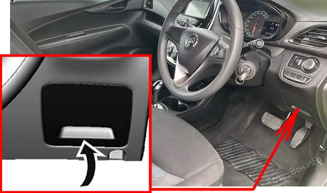
Fuse Box Diagram
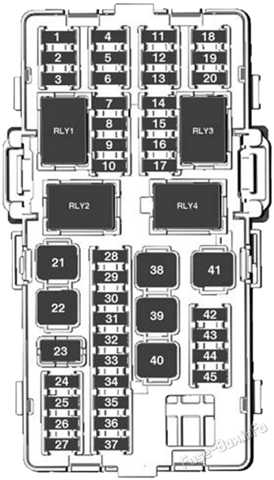
| № | Circuit |
|---|---|
| 1 | Onstar |
| 2 | HVAC module |
| 3 | Instrument panel cluster |
| 4 | Continuously Variable Transmission (CVT) control module |
| 5 | Radio |
| 6 | Body control module 1 (CVT stop & start) |
| 7 | 2019-2020: Side blind spot alert / Rear parking assist |
| 8 | Data link connection |
| 9 | Electric steering column lock |
| 10 | Sensing and Diagnostic module |
| 11 | DC-DC converter |
| 12 | 2019-2020: Virtual Key pass System Module |
| 13 | Electronic toll collection system |
| 14 | Linear power module (NON KOR) |
| 15 | Passive entry & passive start |
| 16 | Discrete logic ignition switch (Non CVT stop & start) |
| 17 | Front collision avoidance |
| 18 | Instrument panel cluster |
| 19 | Reflected LED Alert Display |
| 20 | Headlamp levelling switch |
| 21 | Front power window |
| 22 | Rear power window |
| 23 | - |
| 24 | Automated manual transmission module |
| 25 | Auxiliary power outlet |
| 26 | Sunroof |
| 27 | 2018-2020: Central Gate Module |
| 28 | Body control module 8 |
| 29 | Body control module 7 |
| 30 | Body control module 6 |
| 31 | Body control module 5 |
| 32 | Body control module 4 |
| 33 | Body control module 3 |
| 34 | Body control module 2 (Non CVT stop & start) |
| 35 | Body control module 1 (Non CVT stop & start) |
| 36 | Discrete logic ignition switch (CVT stop & start) |
| 37 | Steering wheel controls backlighting |
| 38 | Linear power module (KOR Only) |
| 39 | Logistic / DC-DC converter |
| 40 | Driver express power window |
| 41 | Blower motor |
| 42 | Front heated seat |
| 43 | HVAC module |
| 44 | Heated steering wheel |
| 45 | Body control module 2 (CVT stop & start) |
| Relays | |
| 1 | Logistic |
| 2 | ACC/RAP |
| 3 | IRAP |
| 4 | RUN |
Advertisements
Engine Compartment Fuse Box
Engine Compartment Fuse Box
Fuse Box Location
To disengage the cover, lift upwards and remove.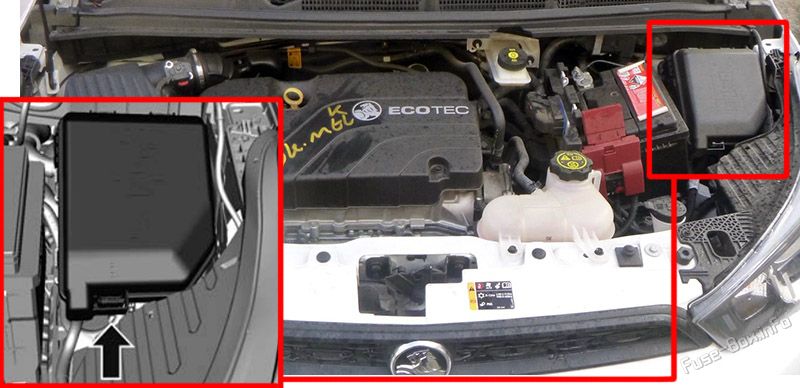
Fuse Box Diagram
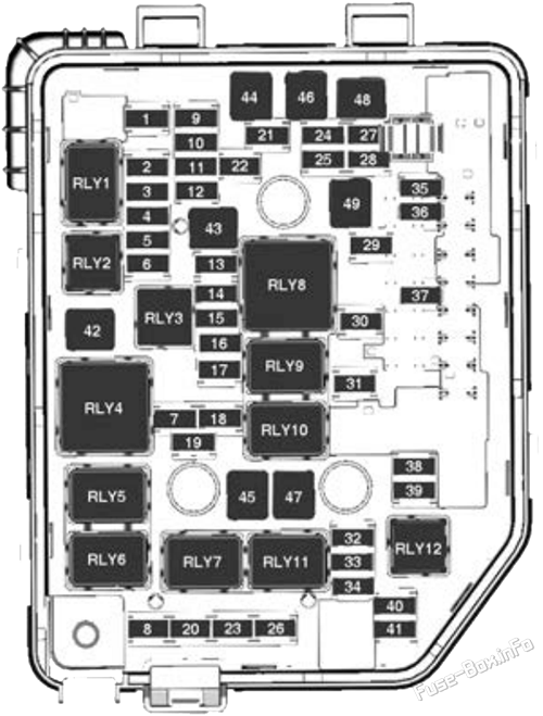
| № | Circuit |
|---|---|
| 1 | Tailgate latch |
| 2 | 2018-2020: Transmission Output Speed Sensor |
| 3 | Rear demist |
| 4 | Outside rear view mirror heater |
| 5 | Sunroof |
| 6 | CVT control module |
| 7 | Mass air flow sensor |
| 8 | 2016-2017: Auxiliary heater pump |
| 9 | ABS valve |
| 10 | Regulated voltage control |
| 11 | Rear view camera |
| 12 | 2020: Central gateway module |
| 13 | - |
| 14 | ECM / TCM |
| 15 | FICM / Starter |
| 16 | Fuel pump motor |
| 17 | ECM 1 |
| 18 | ECM 2 |
| 19 | Injector, Ignition |
| 20 | A/C system |
| 21 | Intelligent battery sensor |
| 22 | Electric steering column lock |
| 23 | Cooling fan low |
| 24 | 2019-2020: Virtual Key pass System Sensor |
| 25 | Outside rear view mirror switch |
| 26 | ECM / Automated manual transmission module |
| 27 | Canister vent solenoid |
| 28 | 2016-2017: Brake pedal switch |
| 29 | Auxiliary occupant sensing |
| 30 | Headlamp levelling motor |
| 31 | Horn |
| 32 | Front fog lamp |
| 33 | High beam left |
| 34 | High beam right |
| 35 | 2019-2020: Air Quality Ioniser |
| 36 | Rear wiper motor |
| 37 | Cornering lamp left |
| 38 | Washer pump motor |
| 39 | Cornering lamp right |
| 40 | - |
| 41 | 2019-2020: Virtual Key pass System Sensor |
| 42 | Starter 2 |
| 43 | In-panel bussed electric centre |
| 44 | Automated manual transmission / DC-DC converter |
| 45 | Starter 1 |
| 46 | Antilock brake system pump |
| 47 | Cooling fan HI |
| 48 | Front wiper motor |
| 49 | In-panel bussed electric centre accessory / RAP power |
| Relays | |
| 1 | Rear demister |
| 2 | TCM |
| 3 | Fuel pump motor |
| 4 | STRTR SOL2 |
| 5 | Air conditioning clutch |
| 6 | 2016-2018: Auxiliary heater pump |
| 7 | Fan lo |
| 8 | RUN/CRNK |
| 9 | PWR/TRN |
| 10 | STRTR SOL1 |
| 11 | Fan HI |
| 12 | Front fog lamp |
Advertisements


 How to check the fuses?
 How to replace a blown fuse?
 Why do car fuses blow?
 Types of automotive fuses