
Advertisements


Fuse Layout Hyundai Elantra 2021-2022..

Table of Contents
Passenger Compartment Fuse Box
Fuse Box Location
The fuse block is located in the driver’s side panel bolster. Inside the fuse/relay box cover, you can find the fuse/relay label describing fuse/ relay names and ratings.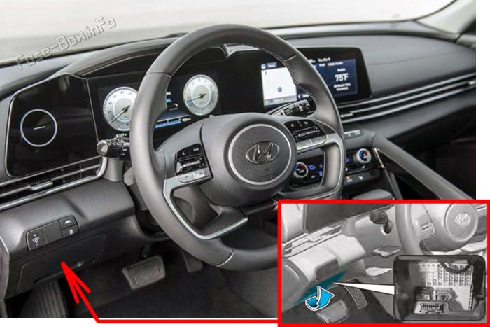
Fuse Box Diagram
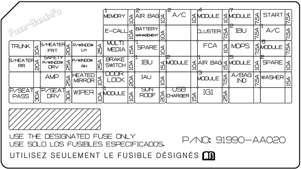
| Fuse Name | Rating | Circuit Protected |
|---|---|---|
| MEMORY1 | 10A | Instrument Cluster, A/C Controller, A/C Control Module, DRV/PASS Folding Outside Mirror |
| AIRBAG2 | 10A | SRS Control Module |
| MODULE4 | 10A | Lane Keeping Assist Unit (LINE), Crash Pad Switch, IBU, Parking Collision Avoidance Assist Unit, A/T Shift Lever Indicator, Front Console Switch |
| MODULE7 | 7.5A | Parking Collision Avoidance Assist Unit, IAU, Rear Seat Warmer Control Module |
| START | 7.5A | Burglar Alarm Relay, Transaxle Range Switch, PCM/ ECMIBU, E/R Junction Block (Start Relay) |
| CLUSTER | 7.5A | Instrument Cluster |
| IBU2 | 7.5A | IBU |
| A/C1 | 7.5A | E/R Junction Block (PTC Heater Relay, Blower Relay), A/C Control Module, A/C Controller |
| TRUNK | 10A | Trunk Lid Latch, Trunk lid Switch |
| S/HEATER FRT | 20A | Front Seat Warmer Control Module |
| P/WINDOW LH | 25A | Power Window Main Switch |
| MULTIMEDIA | 15A | Audio, A/V & Navigation Head Unit, DC-DC Converter |
| FCA | 10A | Forward Collision Avoidance Assist Unit |
| MDPS | 7.5A | MDPS Unit |
| MODULE6 | 7.5A | IBU |
| S/H EATER RR | 20A | Rear Seat Warmer Control Module |
| SAFETY P / WINDOW DRV | 25A | Driver Safety Power Window Module |
| P/WINDOW RH | 25A | Power Window Main Switch, Passenger Power Window Switch |
| BRAKE SWITCH | 10A | Stop Lamp Switch, IBU |
| IBU1 | 15A | IBU |
| MODULE2 | 10A | E/R Junction Block (Power Outlet Relay), AMP, IBU, IAU, Audio, Power Outside Mirror Switch, Parking Collision Avoidance Assist Unit, DC-DC Converter, A/V & Navigation Head Unit |
| AIRBAG1 | 15A | SRS Control Module, Passenger Occupant Detection Sensor |
| MODULE5 | 10A | A/T Shift Lever Indicator, Front Wireless Charger, A/C Controller,Electro Chromic Mirror, A/C Control Module, Audio, A/V & Navigation Head Unit, AMP, DC-DC Converter, Data Link Connector, Rear Seat Warmer Control Module, Front Seat Warmer Control Module |
| AMP | 25A | AMP, DC-DC Converter |
| HEATED MIRROR | 10A | DRV/PAS Outside Mirror Heated, A/C Control Module, A/C Controller |
| DOOR LOCK | 20A | DRV/PAS DOOR ACTUATOR |
| IAU | 10A | BLE Unit, IAU, Driver/Passenger Door NFC Module |
| MODULE3 | 7.5A | Stop Lamp Switch, IAU |
| A/BAG IND | 7.5A | Instrument Cluster, Overhead Console Lamp |
| WASHER | 15A | Multifunction Switch |
| P/SEAT PASS | 30A | Passenger Seat Manual Switch |
| P/SEAT DRV | 30A | Driver Seat Manual Switch |
| WIPER | 10A | PCM/ECM, IBU |
| MODULE1 | 10A | Driver/Passenger Smart Key Outside Handle, Crash Pad Switch, Sport Mode Switch, Data Link Connector, Hazard Switch, Key Solenoid |
| SUNROOF | 20A | Sunroof Motor, Data Link Connector |
| USB CHARGER | 15A | Front USB Charger |
| IG1 | 25A | PCB Block (Fuse - ABS3, ECU5, EOP2, TCU2) |
Advertisements
Engine Compartment Fuse Box
Fuse Box Location
The fuse block is located near the battery. Remove the cover by pressing the tap and pulling up.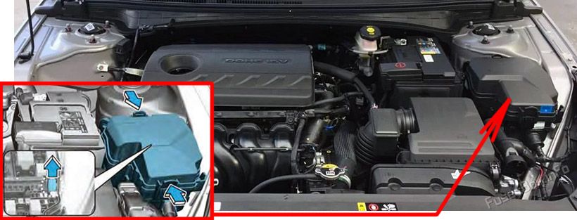
Fuse Box Diagram
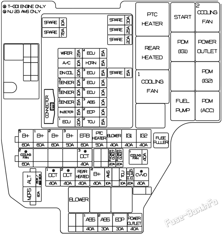
| Fuse Name | Amp. Rating | Circuit Protected |
|---|---|---|
| ALT | 150A/180A | G4NS-W/O AMS2: Alternator, (Fuse - ABS1, ABS2, EOP1, POWER OUTLET1) G4FP/G4NS-Wlth AMS2: Alternator, (Fuse - ABS1, ABS2, EOP1, POWER OUTLET1) |
| MDPS1 | 80A | MDPS Unit |
| B+5 | 60A | PCB Block (Engine Control Relay, Fuse -ECU3, ECU4, HORN, WIPER, A/C) |
| B+1 | 60A | ICU Junction Block (IPS2/IPS5/IPS6/IPS7/ IPS14) |
| B+2 | 60A | ICU Junction Block (IPS1/IPS4/IPS8/IPS9/ IPS10) |
| B+3 | 50 A | ICU Junction Block (Fuse - TRUNK, AMP, SAFETY P/WINDOW DRV, P/SEAT DRV, P/ SEAT PASS, S/HEATER FRT, S/HEATER RR, Long Term Load Latch Relay) |
| EPB | 60A | ESC Control Module |
| PTC HEATER | 50 A | PTC HEATER |
| BLOWER | 40A | BLOWER, DATC |
| IG1 | 40A | E/R Junction Block (PDM (IG1/ACC) Relay), Ignition Switch |
| IG2 | 40A | E/R Junction Block (PDM (IG2) Relay, Start Relay), Ignition Switch |
| POWER OUTLET2 | 20A | Front Power Outlet |
| POWER OUTLET3 | 20A | Not Used |
| COOLING FAN1 | 40A | Cooling Fan |
| DCT1 | 40A | Not Used |
| DCT2 | 40A | Not Used |
| REAR HEATED | 40A | Rear glass heated |
| B+4 | 40A | ICU Junction Block (Fuse - AIR BAG2, IBU1, BRAKE SWITCH, DOOR LOCK, IAU, MODULE1, SUNROOF, Power Window Relay) |
| AMS | 10A | Battery Sensor |
| TCU1 | 10A | [DOT] TCM, [M/T] Ignition Lock Switch |
| FUEL PUMP | 20A | Fuel Pump Control Module (T-GDI), Fuel Pump Motor (NU MPI AKS) |
| CVVD | 40A | Not Used |
| ABS1 | 40A | ABS Control Module, ESC Control Module, Multipurpose Check Connector |
| ABS2 | 30A | ABS Control Module, ESC Control Module, Multipurpose Check Connector |
| EOP1 | 30A | Electronic Oil Pump |
| POWER OUTLET1 | 40A | P/OUTLET FRT |
| WIPER | 25A | Wiper Motor |
| ECU4 | 15A | PCM/ECM |
| A/C | 10A | G4FM: A/C Compressor |
| HORN | 15A | Horn |
| IGN COIL | 20A | Ignition Coil #1~#4 |
| ECU3 | 15A | PCM/ECM |
| SENSOR3 | 10A | E/R Junction Block (Fuel Pump Relay) |
| ECU2 | 10A | Not Used |
| SENSOR2 | 10A | G4NS: Variable Intake Solenoid Valve, Oil Pump Solenoid Valve, Oil Control Valve #1/#2, Canister Close Valve, Purge Control Solenoid Valve, PCB Block (A/C Relay), E/R Junction Block (Cooling Fan1/2 Relay) |
| ECU5 | 10A | ECM/PCM, [MT] Ignition Lock Switch |
| SENSOR1 | 15A | Oxygen Sensor (UP/DOWN) |
| ABS3 | 10A | ABS Control Module, ESC Control Module |
| INJECTOR | 15A | G4FM/G4FG/G4NA: Injector #1~#4 |
| ECU1 | 20A | PCM/ECM |
| TCU2 | 15A | Transaxle Range Switch |
Advertisements