
Advertisements
See other Mercedes-Benz C-Class:


Fuse Layout Mercedes-Benz C-Class 2000-2007

Cigar lighter (power outlet) fuses in the Mercedes-Benz C-Class are the fuse #47 (Front cigar lighter) in the Engine Compartment Fuse Box, and fuse #12 (Interior socket / Power outlet) in the Luggage Compartment Fuse Box.
Table of Contents
Instrument Panel Fuse Box
Instrument Panel Fuse Box
Fuse box location
The fuse box is located on the driver’s side edge of the instrument panel, behind the cover.
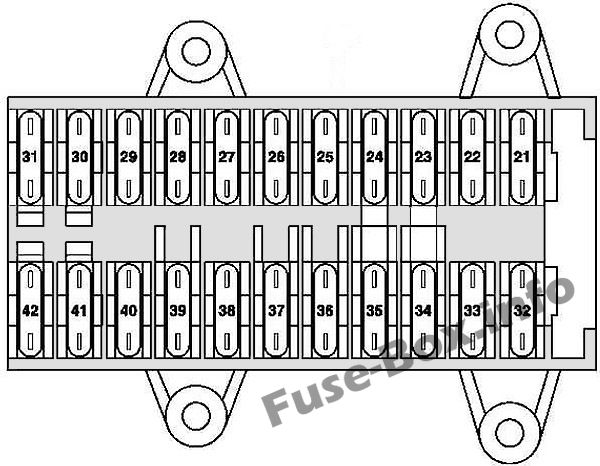
Fuse box diagram
Advertisements
Assignment of the fuses in the instrument panel
| № | Circuit protected | Amp |
|---|---|---|
| 21 | Left front door control unit | 30 |
| 22 | Right front door control unit | 30 |
| 23 | Up to 30.11.04: Central gateway control unit | 15 |
| 24 | CD player with changer (in glove compartment) | 7.5 |
| 25 | Upper control panel control unit | 30 |
| 26 | Sound amplifier | 25 |
| 27 | Driver-side front seat adjustment control unit, with memory Special vehicle multifunction control unit (SVMCU [MSS]) | 30 |
| 28 | Spare | 30 |
| 29 | Driver-side front seat adjustment control unit, with memory Driver-side front seat adjustment control unit, with memory Special vehicle multifunction control unit | 30 |
| 30 | Heating systems recirculation unit | 40 |
| 31 | EIS [EZS] control unit Electric steering lock control unit | 20 |
| 32 | Left rear door control unit | 30 |
| 33 | Right rear door control unit | 30 |
| 34 | Cell phone separation point up to 31.5.01: Telephone and TELE AID transmitter/receiver, D2B Telephone transmitter and receiver unit, D2B Telephone interface E-net compensator up to 31.5.01, Japan version: E-call control unit | 7.5 |
| 34 | up to 31.3.04: Front passenger front seat adjustment control unit with memory as of 1.4.04: Passenger-side front seat adjustment control unit with memory up to 31.5.03, Taxi: Special vehicle multifunction control unit as of 1.6.03, Taxi: Special vehicle multifunction control unit as of 1.6.01, Police: Special vehicle multifunction control unit | 15 |
| 34 | as of 1.4.04: Front passenger front seat adjustment control unit with memory as of 1.4.04, Taxi: Special vehicle multifunction control unit | 30 |
| 35 | up to 31.3.04 : STH heater unit | 30 |
| 35 | as of 1.4.04 : STH heater unit | 20 |
| 36 | up to 31.3.04, Police: Interior socket | 30 |
| 36 | Valid for engine (612.990) (up to 29.2.04): Charge air cooler circulation pump as of 1.4.04, Japan version: Audio gateway control unit | 15 |
| 36 | Universal Portable CTEL Interface (UPCI [UHI]) control unit | 7.5 |
| 37 | Charge air cooler circulation pump up to 29.2.04: Brake booster vacuum pump control unit | 25 |
| 38 | up to 29.2.04:Passenger-side front seat adjustment control unit with memory as of 1.4.04, Police:Special vehicle multifunction control unit (SVMCU [MSS]) | 30 |
| 39 | Spare | 30 |
| 40 | Passenger-side front seat adjustment control unit with memory Universal Portable CTEL Interface (UPCI [UHI]) control unit Cell phone separation point Telephone interface E-net compensator as of 1.6.01, MB standard telephone: Telephone transmitter and receiver unit, D2B as of 1.6.01, TELE AID: Telephone and TELE AID transmitter/receiver, D2B as of 1.6.01, Canadian vehicles: Via the trunk lid/FFS [RBA] separation point the trunk lid emergency release switch and the rear SAM control unit with fuse and relay module USA version: Via the trunk lid/FFS [RBA] separation point the trunk lid emergency release switch and the rear SAM control unit with fuse and relay module as of 1.4.04, Japan version: E-call control unit | 7.5 |
| 40 | up to 31.5.01: Special vehicle multifunction control unit | 30 |
| 41 | HEAT control and operating unit up to 31.5.01: AAC [KLA] control and operating unit Comfort AAC [kLa] control and operating unit | 7.5 |
| 41 | as of 1.6.01: AAC [KLA] control and operating unit Comfort AAC [KLA] control and operating unit | 15 |
| 42 | Instrument cluster | 7.5 |
Engine Compartment Fuse Box
Engine Compartment Fuse Box
Fuse box location
The fuse box is located in the engine compartment (left-side), under the cover.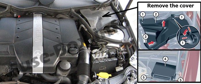
Advertisements
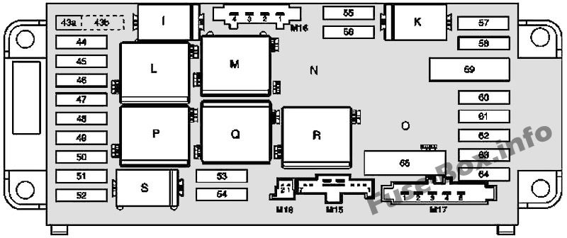
Fuse box diagram
| № | Circuit protected | Amp |
|---|---|---|
| 43a | Fanfare horn relay | 15 |
| 43b | Fanfare horn relay | 15 |
| 44 | Telephone and TELE AID transmitter/ receiver, D2B Telephone transmitter and receiver unit, D2B Cell phone separation point | 5 |
| 45 | Restraint systems control unit | 7.5 |
| 46 | Wiper ON/OFF relay Wiper speed 1 and 2 relay | 40 |
| 47 | Glove compartment illumination with switch Front cigar lighter (with illumination) | 15 |
| 48 | Valid for engine 612.990 (up to 31.3.04): Brake booster vacuum pump control unit Valid for engine 112 and engine 113: Circuit 15 connector sleeve (fused) Valid for engine 646, USA version (up to 31.3.04): Circuit 30 connector sleeve Valid for engine 646 (as of 1.4.04): O 2 sensor upstream of TWC [kAt] connector | 15 |
| 49 | Restraint systems control unit | 7.5 |
| 50 | Light switch module Valid for engine 612.990: Glow output stage (up to 31.3.04), Hot film mass air flow sensor (1.4.04 up to 30.11.04) | 5 |
| 51 | AAC with integrated control additional fan motor Instrument cluster Valid for code (581) comfort automatic air conditioning: C-AAC [K-KLA] multifunction sensor, C-AAC [K-KLA] sun sensor (4 in total), Left front lamp unit, Right front lamp unit Valid for AMG vehicles: Charge air cooler circulation pump Valid for model 203.0 (up to 31.7.01): SPS [PML] control unit | 7.5 |
| 52 | Starter | 15 |
| 53 | Starter relay Rear SAM control unit with fuse and relay module Valid for engine 611/612/642/646: CDI control unit | 25 |
| 53 | Valid for gasoline engines: Starter relay Rear SAM control unit with fuse and relay module Valid for engine 111/271/272: ME-SFI [ME] control unit Valid for engine 112/113: ME-SFI [ME] control unit Circuit 87M1e connector sleeve | 15 |
| 54 | Valid for engine 271.940: ME-SFI [ME] control unit Purge control valve (USA version) Activated charcoal canister shutoff valve Valid for engine 271.942: NOX (nitrogen oxides) control unit Valid for engine 642/646: CDI control unit Valid for engine 642/646: Circuit 30 connector sleeve | 15 |
| 54 | Valid for engines 611/612: CDI control unit Valid for engine 611/612 (up to 30.11.04): Vent line heater element | 7.5 |
| 55 | Steering angle sensor Distronic: DTR control unit Valid for transmission 722: ETC [EGS] control unit (up to 31.5.04) Electronic selector lever module control unit Electric controller unit (VGS) Valid for transmission 716: Gear recognition switch Automated manual transmission control unit | 7.5 |
| 56 | ESP and BAS control unit Stop light switch | 5 |
| 57 | Steering angle sensor (up to 31.5.02) EIS [EZS] control unit Steering column module (as of 1.6.02) Valid for engine 112/113: ME-SFI [ME] control unit | 5 |
| 58 | Valid for transmission 716: SEQ hydraulic pump | 40 |
| 59 | ESP and BAS control unit | 50 |
| 60 | ESP and BAS control unit | 40 |
| 61 | Valid for transmission 716: Automated manual transmission control unit | 15 |
| 62 | Data link connector Light switch module Stop light switch | 5 |
| 63 | Light switch module | 5 |
| 64 | Radio Radio and navigation unit COMAND operating, display and control unit | 10 |
| 65 | Valid for engine 112/113: Electric air pump | 40 |
| Relay | ||
| I | Fanfare horn system relay | |
| K | Terminal 87 relay, chassis | |
| L | Wiper speed 1 and 2 relay | |
| M | Terminal 15R relay | |
| N | SEQ [ASG] pump control relay (with Sequentronic automated manual transmission (ASG)) | |
| O | Air pump relay (engines 112, 113, 271 only) | |
| P | Terminal 15 relay | |
| Q | Wiper ON/OFF relay | |
| R | Terminal 87 relay, engine | |
| S | Starter relay |
Advertisements
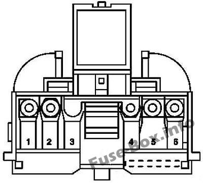
Front Prefuse Box
Front Prefuse Box
| № | Circuit protected | Amp |
|---|---|---|
| 1 | Interior fusebox | 125 |
| 2 | Luggage fusebox | 200 |
| 3 | Additional fuse holder 1, spare wheel well | 125 |
| 4 | Engine fusebox | 200 |
| 5 | Engine and AC electric suction fan with integrated control Valid for diesel engines: Glow output stage | 125 |
| 6 | Engine fusebox | 60 |
Luggage Compartment Fuse Box
Luggage Compartment Fuse Box
Fuse box location
The fuse box is located in the luggage compartment (on the left-side), behind the cover.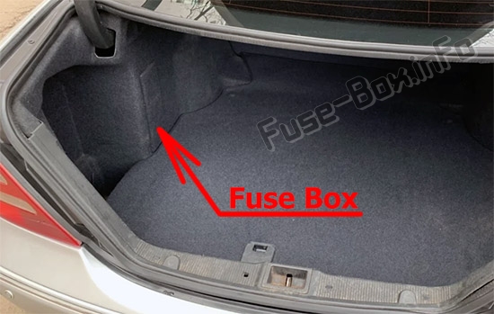
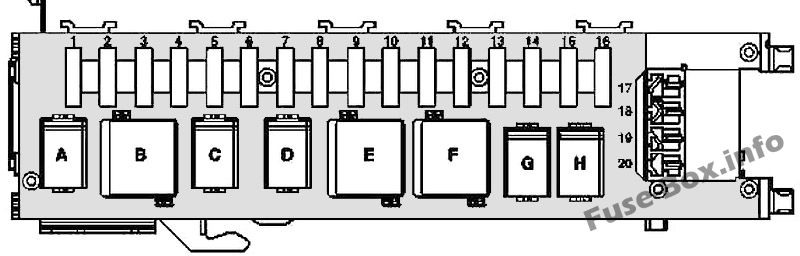
Fuse box diagram
Advertisements
Assignment of the fuses and relay in the trunk
| № | Circuit protected | Amp |
|---|---|---|
| 1 | Front passenger front seat adjustment control unit with memory Front passenger partially-electric seat adjustment switch | 30 |
| 2 | Driver front seat adjustment control unit with memory Driver partially-electric seat adjustment switch | 30 |
| 3 | Dome lamp Right luggage compartment lamp Left luggage compartment lamp STH radio remote control receiver | 7.5 |
| 3 | TV tuner (up to 29.2.04) TV tuner (MOST) (as of 1.4.04) | 20 |
| 4 | Fuel pump relay (N10/2kA) | 20 |
| 5 | Valid for engine 112.961 (up to 31.3.04): Charge air cooler circulation pump Valid without engine 112.961: Backup relay 2 | 20 |
| 6 | Spare | 25 |
| 7 | Backup relay 1 | 7.5 |
| 8 | Amplifier module, window antenna Alarm signal horn (H3) ATA [EDW] inclination sensor | 7,5 |
| 9 | Overhead control panel control unit | 25 |
| 10 | Heated rear window | 40 |
| 11 | Spare | 20 |
| 12 | Interior socket Valid for model 203.0 USA version (up to 31.3.04): Power outlet | 15 |
| 13 | Multicontour seat pneumatic pump Voice control system control unit Rear dome lamp Rear dome lamp PTS warning indicator PTS control unit Japan version: VICS+ETC voltage supply separation point. | 5 |
| 14 | Tailgate wiper motor | 15 |
| 15 | Fuel filler cap polarity change relay 1 Fuel filler cap polarity change relay 2 | 10 |
| 16 | Voice control system control unit | 20 |
| 17 | Trailer recognition control unit | 20 |
| 18 | Trailer hitch socket (13-pin) | 20 |
| 19 | Multicontour seat pneumatic pump | 20 |
| 20 | Rear window roller blind relay Valid for model 203.2/7 USA version: Power outlet | 15 |
| Relay | ||
| A | Fuel pump relay | |
| B | Relay 2, terminal 15R | |
| C | Reserve relay 2 | |
| D | Reserve relay 1 | |
| E | Rear window defroster relay | |
| F | Relay 1, terminal 15R | |
| G | Filler cap relay, polarity reverser 1 | |
| H | Filler cap relay, polarity reverser 2 |
Advertisements