
Advertisements
See other Mercedes-Benz CLS-Class:

Fuse Layout Mercedes-Benz CLS-Class 2004-2010

Cigar lighter (power outlet) fuses in the Mercedes-Benz CLS-Class are the fuses #12 (Luggage compartment socket), #13 (Interior socket) in the Luggage Compartment Fuse Box, and fuses #54a, #54b (cigar lighters) in the Engine Compartment Fuse Box.
Table of Contents
Instrument Panel Fuse Box
Instrument Panel Fuse Box
Fuse box location
The fuse box is located on the left side of the instrument panel, behind the cover.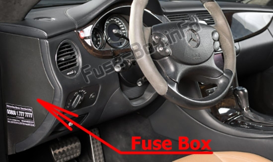
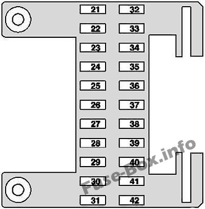
Fuse box diagram
Advertisements
Assignment of the fuses in the instrument panel
| № | Fused function | Amp |
|---|---|---|
| 21 | Right rear door control unit | 30 |
| 22 | Right front door control unit | 30 |
| 23 | Passenger-side front seat adjustment control unit with memory | 30 |
| 24 | Rear module Keyless Go control unit Left rear door Keyless Go control unit Right rear door Keyless Go control unit | 25 |
| 25 | Stationary heater (STH) unit | 20 |
| 25 | Additionally fused via polyswitch fuse for stationary heater: STH radio remote control receiver | 5 |
| 26 | CD changer | 7.5 |
| 27 | Spare | - |
| 28 | Radio | 15 |
| 28 | Radio control panel and navigation unit COMAND operating, display and controller unit | 5 |
| 29 | Steering column module Rotary light switch EIS [EZS] control unit | 7.5 |
| 30 | Data link connector | 7.5 |
| 31 | Upper control panel control unit Cutoff relay for interruptible loads (up to 2007) | 5 |
| 32 | Left rear door control unit | 30 |
| 33 | Left front door control unit | 30 |
| 34 | Driver-side front seat adjustment control unit, with memory | 30 |
| 35 | WSS (Weight Sensing System) control unit | 5 |
| 36 | HS [SIH] and seat ventilation control unit Right SAM control unit | 25 |
| 37 | AIRmatic with ADS control unit | 15 |
| 38 | NECK-PRO head restraints relay | 7.5 |
| 39 | Lower control panel control unit | 5 |
| 40 | HS [SIH] and seat ventilation control unit | 10 |
| 41 | Central gateway control unit | 5 |
| 42 | ME-SFI [ME] control unit Driver-side SAM control unit with fuse and relay module | 7.5 |
Luggage Compartment Fuse Box
Luggage Compartment Fuse Box
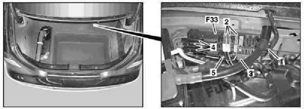
Fuse box location
It is located on the left side of the luggage compartment, behind the cover.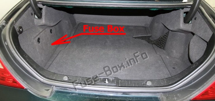
Advertisements
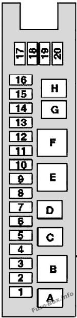
Fuse box diagram
| № | Fused function | Amp |
|---|---|---|
| 1 | Front passenger partially-adjustment switch Driver partially-electric seat adjustment switch (as of 2007) Driver-side front seat adjustment control unit, with memory | 30 |
| 2 | Driver partially-electric seat adjustment switch Front passenger partially-electric seat adjustment switch (as of 2007) Passenger-side front seat adjustment control unit with memory | 30 |
| 3 | TPM [RDK] (tire pressure monitor) control unit PTS (Parktronic) control unit Navigation processor TV combination tuner (analog/digital) | 7.5 |
| 4 | Except engine 156.983 (CLS 55 AMG) and engine 272.985 : The fuel pump is fused via the fuel pump relay | 20 |
| 4 | Valid for engine 113.990 (CLS 55 AMG): The charge air cooler circulation pump is fused via the charge air cooler circulation pump relay | 7.5 |
| 5 | Spare relay 2 | - |
| 6 | Audio gateway control unit | 40 |
| 7 | Rear wiper relay | 15 |
| 8 | Left antenna amplifier module Alarm horn Alarm signal horn with additional battery ATA [EDW] inclination sensor | 7.5 |
| 9 | Overhead control panel control unit | 25 |
| 10 | Heated rear window | 40 |
| 11 | - | 20 |
| 12 | USA version: Luggage compartment socket | 15 |
| 13 | Interior socket | 15 |
| 14 | - | 5 |
| 15 | Fuel filler flap CL [ZV] motor | 10 |
| 16 | HS [SIH] and seat ventilation control unit | 20 |
| 17 | - | 20 |
| 18 | - | 20 |
| 19 | Multicontour seat pneumatic pump | 20 |
| 20 | Rear window roller blind relay | 7.5 |
| Relays | ||
| A | Fuel pump relay (except 113.990 (CLS 55 AMG), 156.983 (CLS 63 AMG), 272.985) Charge air cooler circulation pump relay (113.990 (CLS 55AMG)) | |
| W | Relay 2, terminal 15R | |
| C | Spare relay 2 | |
| D | Spare | |
| E | Heated rear window relay | |
| F | Relay 1, terminal 15R | |
| G | Fuel filler cap polarity reverser relay 1 | |
| H | Fuel filler cap polarity reverser relay 2 |
Engine Compartment Fuse Box
Engine Compartment Fuse Box
Fuse box location
The fuse box is located in the engine compartment (left-side)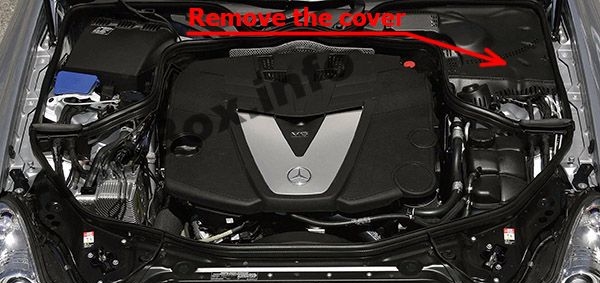
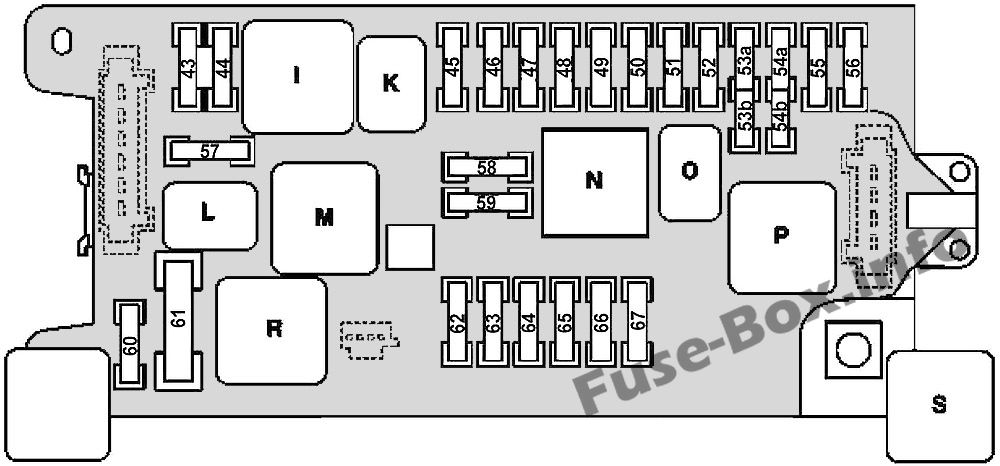
Fuse box diagram
Advertisements
Assignment of the fuses and relay in the engine compartment
| № | Fused function | Amp |
|---|---|---|
| 43 | Valid for M156, M272, M273: ME-SFI [ME] control unit Rear SAM control unit with fuse and relay module Valid for M642: CDI control unit Rear SAM control unit with fuse and relay module Valid for M113: ME-SFI [ME] control unit Rear SAM control unit with fuse and relay module Fuel pump relay Air injection relay | 15 |
| 44 | Valid for M642: CDI control unit | 15 |
| 45 | AIRmatic with ADS control unit | 7.5 |
| 46 | Automatic 5-speed transmission (NAG): ETC [EGS] control unit 7-speed automatic transmission: Electric controller unit (VGS) | 7.5 |
| 47 | ESP control unit | 5 |
| 48 | Restraint systems control unit | 7.5 |
| 49 | Left front reversible emergency tensioning retractor (as of 2007) Right front reversible emergency tensioning retractor (as of 2007) Restraint systems control unit (up to 2007) Front passenger seat occupied and child seat recognition sensor (up to 2007) NECK-PRO head restraints relay (2006) | 7.5 |
| 50 | VICS power supply separation point | 5 |
| 51 | - | 5 |
| 52 | Glove compartment illumination with switch Instrument cluster Rotary light switch Bi-xenon headlamp unit: Headlamp range adjustment control unit | 7.5 |
| 53a | Fanfare horn relay | 15 |
| 53b | Fanfare horn relay | 15 |
| 54a | Illuminated cigar lighter | 15 |
| 54b | Illuminated cigar lighter | 15 |
| 55 | VICS power supply separation point | 7.5 |
| 56 | Wiper motor | 40 |
| 57 | Valid for M156, M272, M273: ME-SFI [ME] control unit Rear SAM control unit with fuse and relay module Valid for engine M642: CDI control unit Rear SAM control unit with fuse and relay module | 25 |
| 58 | Purge control valve (up to 2007) Valid for engine 272: AAC with integrated control additional fan motor (up to 2007) USA version: Activated charcoal canister shutoff valve (up to 2007) Activated charcoal filter shutoff valve (up to 2007) Valid for engine 642: CDI control unit (2006) Valid for engine M113, M156, M272, M273: Cylinder 1 ignition coil Cylinder 2 ignition coil Cylinder 3 ignition coil Cylinder 4 ignition coil Cylinder 5 ignition coil Cylinder 6 ignition coil Cylinder 7 ignition coil Cylinder 8 ignition coil Valid for engine M113: Left O2 sensor downstream TWC [KAT] Right O2 sensor downstream TWC [KAT] | 15 |
| 59 | Starter relay | 15 |
| 60 | Valid for engine 113.990 (CLS 55 AMG), 156.983 (CLS 63 AMG): Oil cooler fan | 10 |
| 61 | Electric air pump | 40 |
| 62 | Backup relay | 30 |
| 63 | - | 15 |
| 64 | Rotary light switch Comfort automatic air conditioning control and operating unit Instrument cluster (up to 2007) AAC [KLA] control and operating unit (up to 2007) | 7.5 |
| 65 | EIS [EZS] control unit Electric steering lock control unit | 20 |
| 66 | Valid for left-hand drive vehicles: Right front lamp unit Valid for right-hand drive vehicles: Left front lamp unit Bi-xenon headlamp unit: HRA power module | 7.5 |
| 67 | Stop light switch | 10 |
| Relays | ||
| I | Terminal 87 relay, engine | |
| K | Terminal 87 relay, chassis | |
| L | Starter relay | |
| M | Backup relay | |
| N | Terminal 15 relay | |
| O | Fanfare horn relay | |
| P | Terminal 15R relay | |
| R | Air pump relay (except engine 113.990 (CLS 55 AMG) and 156.983 (CLS 63 AMG)) Oil cooler fan relay (only engine 113.990 (CLS 55 AMG) and 156.983 (CLS 63 AMG)) | |
| S | AIRmatic relay (semi-active air suspension) |
Advertisements
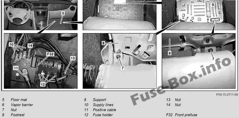
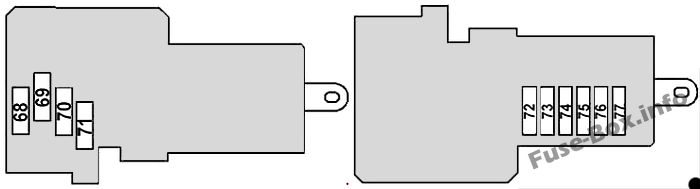
Front Pre-Fuse Box
Front Pre-Fuse Box
| № | Fused function | Amp |
|---|---|---|
| 68 | PTC heater booster (as of 1.6.06) | 200 |
| 69 | - | 150 |
| 70 | Additional battery relay (up to 31.5.06) | 150 |
| 71 | AAC with integrated control additional fan motor | 150 |
| 72 | SBC hydraulic unit (up to 31.5.06) ESP control unit (as of 1.6.06) | 50 |
| 73 | SBC hydraulic unit (up to 31.5.06) ESP control unit (as of 1.6.06) | 40 |
| 74 | AIRmatic relay | 40 |
| 75 | Right SAM control unit | 40 |
| 76 | Right front reversible emergency tensioning retractor (as of 1.6.06) | 40 |
| 77 | Heating systems recirculation unit | 40 |
Advertisements
Rear Pre-fuse Box
Rear Pre-fuse Box
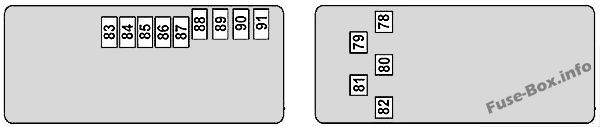
| № | Fused function | Amp |
|---|---|---|
| 78 | Driver-side SAM control unit with fuse and relay module | 200 |
| 79 | Rear SAM control unit with fuse and relay module | 200 |
| 80 | Driver SAMcontrol unit with fuse and relay module | 150 |
| 81 | Interior fuse box | 150 |
| 82 | AMG vehicles: FP fuse (F82A), Air injection fuse (F82B) | 150 |
| F82A | Left fuel pump control unit Right fuel pump control unit | 30 |
| F82B | Air injection relay | 40 |
| 83 | - | 30 |
| 84 | Battery sensor (as of 2007) Battery control unit (up to 2007) | 5 |
| 85 | Voice control system (VCS [SBS]) control unit Universal Portable CTEL Interface (UPCI [UHI]) control unit Japan version: GPS box control unit Microphone array control unit USA version: CTEL [TEL] compensator, data E-net compensator | 5 |
| 86 | USA version: SDAR control unit (up to 2007) | 5 |
| 87 | Pneumatic pump for dynamic seat control | 30 |
| 88 | TLC [HDS] control unit | 30 |
| 89 | - | 40 |
| 90 | Left front reversible emergency tensioning retractor (as of 2007) | 40 |
| 91 | Valid with engine 272.985: Fuel pump control unit (as of 2007) | 30 |
Advertisements