Advertisements
See other MG HS:
Fuse Layout MG eHS 2020-2023
Table of Contents
Passenger Compartment Fuse Box
Passenger Compartment Fuse Box
Fuse Box Location
The fuse panel is located behind the right dashboard panel cover. Remove the driver side dashboard panel cover to access the fuse box.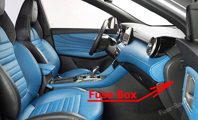
Fuse Box Diagram
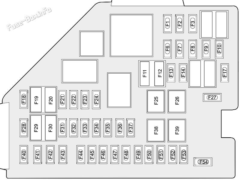
| № | Amps | Function |
|---|---|---|
| F1 | 10A | Sensing Diagnostic Module (Airbag), Electronic Shifter Control Unit, TBOX, Instrument Pack, Body Control Module, Airbag Display Module |
| F2 | 7.5A | Engine Control Module, Hybrid Control Unit |
| F3 | 5.0A | Front View Control Module, Front Detection Radar |
| F6 | - | - |
| F7 | 15A | Towing Kit Connector Socket |
| F8 | 15A | Front Power Socket |
| F9 | 5A | USB Port |
| F10 | - | - |
| F11 | 7.5A | Mirror Heaters |
| F12 | 25A | Rear Windscreen Heating |
| F13-F14 | - | - |
| F17 | - | - |
| F18 | 30A | Rear Left Window Lift |
| F19 | 5A | EPB Switch, PRND Display |
| F20 | 30A | Rear Right Window Lift |
| F21 | 10A | Front Right Seat Heating Relay |
| F22 | 5A | Diagnostic Line Connector |
| F23 | 10A | Front Left Seat Heating Relay |
| F24 | 10A | Gateway |
| F25 | 40A | KLR Relay |
| F26 | 30A | Passenger Window lift |
| F27 | - | - |
| F28 | 5A | Passive Entry Passive Start Module, Backup Immobilizer Coil |
| F29 | 10A | Gateway |
| F30 | 5A | Driver Door Switch Pack, Rain Light Sensor |
| F31 | - | - |
| F32 | 5A | Ambient Light Control Module |
| F33 | 5A | Sensing Diagnostic Module (Airbag) |
| F34 | 5A | TBOX |
| F35 | 10A | Radio Broadcasting Reception Module |
| F36 | 10A | Electronic Steering Column Lock |
| F37 | 20A | Driver Electric Adjust Seat Switch |
| F38 | 30A | Driver Window Lift |
| F39 | 30A | Blower |
| F40 | 15A | Entertainment System |
| F41 | 5A | Upper Console Switch |
| F42 | 10A | AC Control Module |
| F43 | 5A | Instrument Pack |
| F44 | 5A | Rear Driving Assistance System |
| F45 | 30A | Sunroof Motor |
| F46 | 5A | Tyre Pressure Monitoring System |
| F47 | 30A | Sunshade Motor |
| F48 | 20A | Passenger Electric Adjust Seat |
| F49 | 5A | Around View Module |
| F50 | - | - |
| F51 | 30A | Rear Windscreen Heating Relay, Exterior Mirrors Relay |
| F52 | 10A | Headlamp, Interior Rear View Mirror, Headlamp Levelling Switch |
| F53 | 10A | Electronic Shifter Control Unit |
| F54 | - | - |
Advertisements
Engine Compartment Fuse Box
Engine Compartment Fuse Box
Fuse Box Location
Press the lock catch to open the upper cover of front compartment fuse box.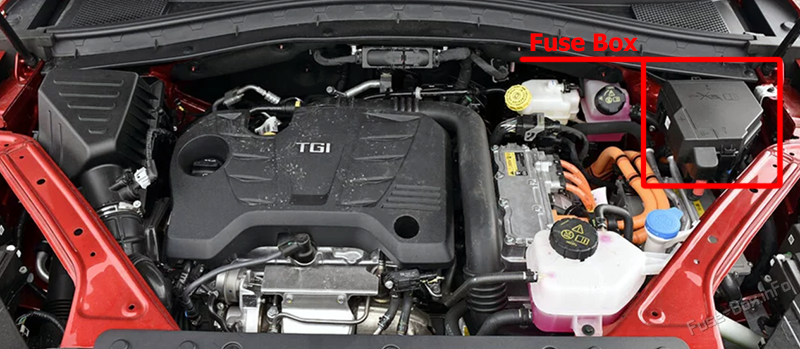
Fuse Box Diagram
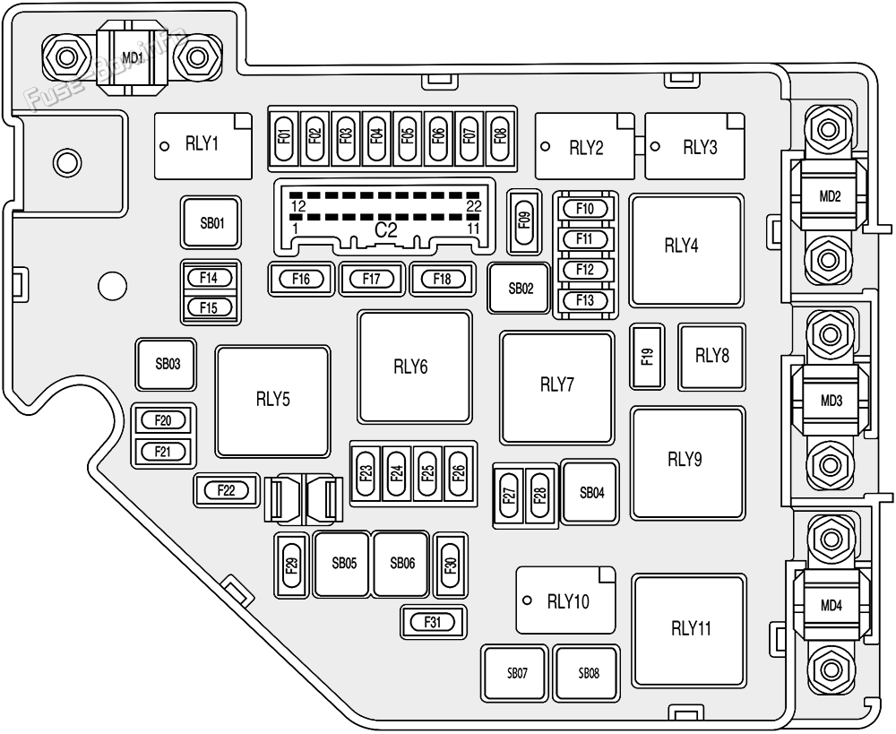
| № | Amps | Function |
|---|---|---|
| F01 | 10A | Right Headlamp Assembly |
| F02 | 10A | Left Headlamp Assembly |
| F03 | 10A | DC/DC Convertor |
| F04 | - | - |
| F05 | 5A | Electric Air Conditioning Compressor |
| F06-F07 | - | - |
| F08 | 20A | Power Electronic Box Coolant Pump |
| F09 | 10A | Fuel Pump Relay, Lower Console Switch, Fuel Tank Isolation Diagnosis Module (Tank Leakage), Brake Pedal Switch |
| F10 | 20A | Engine Control Module |
| F11 | 15A | Intake Variable Camshaft Timing, Exhaust Variable Camshaft Timing, Upstream Lambda Sensor, Downstream Lambda Sensorv Canister Purge Valve |
| F12 | 20A | Ignition Coil |
| F13 | 15A | Waste Gate Control Valve, Dump Valve, Electronic Thermostat, Mass Air Flow Sensor |
| F14 | 25A | Body Control Module |
| F15 | 10A | Rear Washer Relay |
| F16 | 25A | Body Control Module |
| F17 | 25A | Body Control Module |
| F18 | 25A | Body Control Module |
| F19 | 10A | Front Fog Lamp Relay |
| F20 | 10A | Front Washer Relay |
| F21 | 10A | Engine Control Module |
| F22 | 10A | Power Electronic Box |
| F23-F24 | - | - |
| F25 | 30A | Hybrid Control Unit |
| F26 | 25A | Body Control Module |
| F27 | - | - |
| F28 | 10A | Engine Auxiliary Pump |
| F29 | 15A | Horn |
| F30 | 10A | Hybrid Control Unit |
| F31 | 25A | Front Wiper Enable Relay |
| SB01 | 25A | Body Control Module |
| SB02 | 60A | Cooling Fan Low Speed Relay |
| SB03 | 40A | EVP Relay |
| SB04 | 40A | Cooling Fan |
| SB05 | 40A | Stability Control System-Pump |
| SB06 | 40A | Stability Control System-Valve |
| SB07 | - | - |
| SB08 | 50A | Cooling Fan Middle Speed Relay |
| MD1 | 200A | Power Pump |
| MD2 | 100A | Passenger Compartment Fusebox |
| MD3 | 80A | Electric Power Steering Module |
| MD4 | 200A | Luggage Compartment Fusebox |
Advertisements
Luggage Compartment Fuse Box
Luggage Compartment Fuse Box
Fuse Box Location
Move the luggage compartment carpet assembly, and open the cover plate of the luggage compartment fuse box marked with Fuse Box. Loosen the two clips at the front and the rear of the fuse box, and open the cover plate of the luggage compartment fuse box.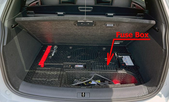
Fuse Box Diagram
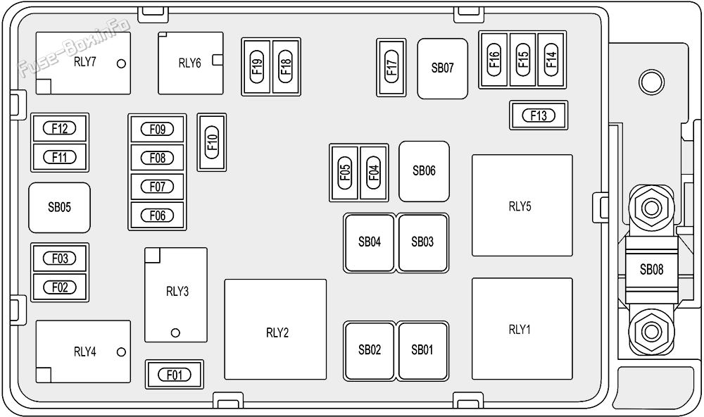
| № | Amps | Function |
|---|---|---|
| F01 | 20A | Super Lock Relay |
| F02 | - | - |
| F03 | 20A | ESS Coolant Pump Relay |
| F04-F07 | - | - |
| F08 | 15A | Towing Kit Connector Socket |
| F09 | 5A | Electrical Battery Sensor |
| F10 | 15A | Rear Wiper Relay |
| F11-F12 | - | - |
| F13 | 5A | Pedestrian Alert Control Module |
| F14 | - | - |
| F15 | 10A | Chassis Management Module |
| F16 | - | - |
| F17 | 20A | Energy Storage System, On-Board Charger |
| F18 | - | - |
| F19 | 15A | Fuel Pump Relay |
| SB01 | 30A | Positive Temperature Coefficient |
| SB02 | 30A | Positive Temperature Coefficient |
| SB03-SB04 | - | - |
| SB05 | 30A | Power Liftgate Control Module |
| SB06 | 30A | Positive Temperature Coefficient |
| SB07 | - | - |
| SB08 | 200A | Battery Power |
Advertisements


 How to check the fuses?
 How to replace a blown fuse?
 Why do car fuses blow?
 Types of automotive fuses