
Advertisements
Fuse Layout Skoda Citigo-e iV
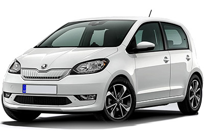
Table of Contents
Passenger Compartment Fuse Boxes
Passenger Compartment Fuse Boxes
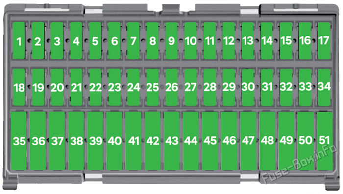
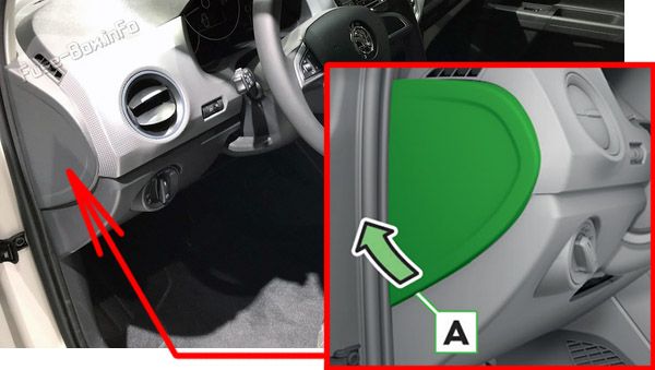
Fuses in the dash panel
The fuses are located below the instrument panel.
Push the fuse lug A downwards and open the fuse box cover. Switch the fuse with clip B.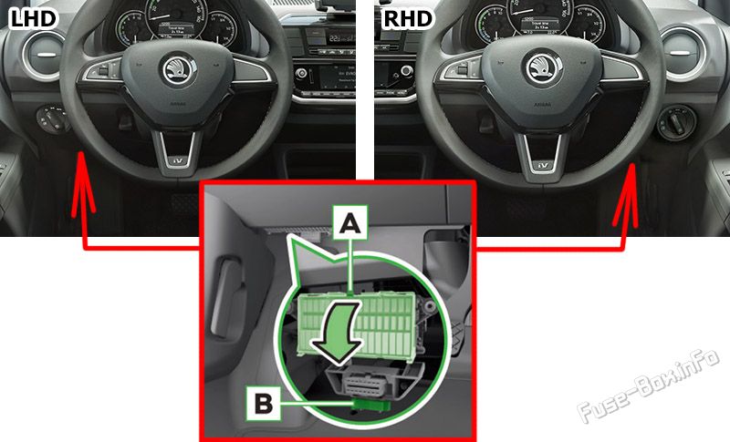
Fuse Box Diagram
| № | Amps | Function/component |
|---|---|---|
| 1 | 7.5A | Dash panel insert Engine control unit |
| 2 | 7.5A | High-voltage battery 1 Diagnostic connection |
| 3 | 7.5A | Rear view camera |
| 4 | - | - |
| 5 | 7.5A | Steering column electronics control unit Onboard supply control unit |
| 6 | 7.5A | Mirror adjustment switch Headlight range control regulator Left headlight range control motor Right headlight range control motor |
| 7 | 10A | Power and control electronics for electric drive |
| 8 | 7.5A | Selector lever Brake servo control unit Charge voltage control unit for high-voltage battery Power and control electronics for electric drive |
| 9 | 7.5A | Front passenger side airbag deactivated warning lamp Airbag control unit |
| 10 | 7.5A | Control unit for the parking aid |
| 11 | 7.5A | Front camera for driver assistance systems |
| 12 | - | - |
| 13 | - | - |
| 14 | 15A | Rear window wiper motor |
| 15 | 10A | Light switch |
| 16 | 7.5A | Terminal 15 voltage supply relay Power-assisted steering control unit |
| 17 | 15A | Steering column electronics control unit |
| 18 | 15A | Charging unit 1 for high-voltage battery |
| 19 | - | - |
| 20 | 7.5A | ABS control unit Steering column electronics control unit |
| 21 | - | - |
| 22 | - | - |
| 23 | 7.5A | Engine control unit |
| 24 | 15A | Steering column electronics control unit Headlight flasher switch |
| 25 | 10A | Windscreen and rear window washer pump |
| 26 | 7.5A | Main relay Dash panel insert |
| 27 | 7.5A | Onboard supply control unit Interior light |
| 28 | 7.5A | Diagnostic connection |
| 29 | 7.5A | Onboard supply control unit |
| 30 | 7.5A | Onboard supply control unit Heated exterior mirror on driver side Heated exterior mirror on passenger side |
| 31 | 10A | Radiator fan |
| 32 | 15A | Onboard supply control unit Turn signal/brake light |
| 33 | - | - |
| 34 | - | - |
| 35 | - | - |
| 36 | 20A | Cigarette lighter |
| 37 | 15A | Engine sound generator control unit |
| 38 | 20A | Radio |
| 39 | - | - |
| 40 | 15A | Engine control unit |
| 41 | 20A | Onboard supply control unit Central locking |
| 42 | 20A | Coolant pump for high-temperature circuit Coolant circulation pump upstream of power and control electronics for electric drive |
| 43 | 20A | Centre switch module in dash panel Centre switch module 2 in dash panel Heated front seats control unit |
| 44 | 7.5A | High-voltage battery 1 |
| 45 | 10A | Light switch |
| 46 | 30A | Onboard supply control unit Heated rear window |
| 47 | 30A | Front right window regulator switch Operating unit for window lifter in driver door (RHD) Driver side central locking lock unit |
| 48 | 20A | Onboard supply control unit High-frequency horn Low frequency horn |
| 49 | 30A | Onboard supply control unit Wiper motor control unit |
| 50 | 20A | Onboard supply control unit Left tail light cluster Left reversing light bulb Right tail light cluster Right reversing light bulb |
| 51 | 30A | Operating unit for window regulator in driver door Driver side central locking unit (RHD) |
Advertisements
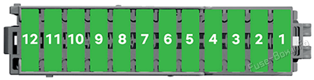
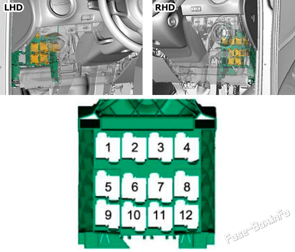
Fuses behind the side cover of the dash panel
- Insert a slotted screwdriver in the area A under the side cover of the control panel and release the cover.
- Remove the cover.
Fuse Box Diagram
| № | Amps | Function/component |
|---|---|---|
| 1 | 7.5A | Control unit for emergency call module and communication unit |
| 2 | 30A | Brake system pressure accumulator |
| 3 | 7.5A | Solenoid valve for ignition key withdrawal lock |
| 4 | 20A | Blower relay |
| 5 | 7.5A | Climatronic relay |
| 6 | 10A | Emergency cut-out connection Maintenance connector for high-voltage system |
| 7 | 7.5A | Climatronic control unit |
| 8 | 7.5A | Selector lever Rain and light sensor Charge voltage control unit for high-voltage battery |
| 9 | 15A | Onboard supply control unit Low beam/daytime running lights/high beam |
| 10 | 15A | Onboard supply control unit Low beam/daytime running lights/high beam |
| 11 | 30A | Heated windscreen relay |
| 12 | 30A | Heated windscreen relay 2 |
Relay panel
| № | Relay |
|---|---|
| 1 | Terminal 75 voltage supply relay 1 |
| 2 | Terminal 15 voltage supply relay |
| 3 | Heated windscreen relay |
| 4 | Main relay |
| 5 | not assigned |
| 6 | Heated windscreen relay 2 |
| 7 | Climatronic relay |
| 8 | not assigned |
| 9 | not assigned |
| 10 | Blower relay |
| 11 | not assigned |
| 12 | not assigned |
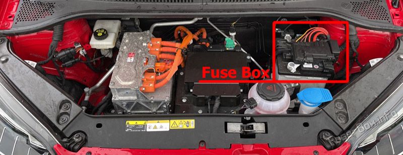
Engine Compartment Fuse Box
Engine Compartment Fuse Box
Fuse Box Location
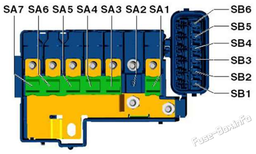
Fuse Box Diagram
| № | Amps | Function/component |
|---|---|---|
| SA1 | 250A | Power and control electronics for electric drive |
| SA2 | - | - |
| SA3 | 150A | Fuse holder C (below the instrument panel) Fuse holder D (at the end of the instrument panel) Terminal 15 voltage supply relay |
| SA4 | 50A | Power-assisted steering control unit |
| SA5 | 40A | ABS control unit |
| SA6 | 40A | Radiator fan |
| SA7 | 50A | Brake servo control unit |
| SB1 | 30A | ABS/ESC control unit |
| SB2 | 7.5A | Brake servo control unit |
| SB3 | 7.5A | Ignition starter switch / Control lever under the steering whee |
| SB4 | 10A | ABS/ESC control unit |
| SB5 | 7.5A | Battery monitor control unit Onboard supply control unit |
| SB6 | 30A | Ignition starter switch |
Advertisements