Advertisements
Fuse Layout Toyota Highlander Hybrid 2006-2007
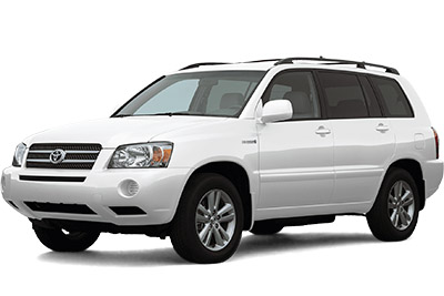
Table of Contents
Passenger Compartment Fuse Box
Passenger Compartment Fuse Box
Fuse Box Location
Remove the lid to access.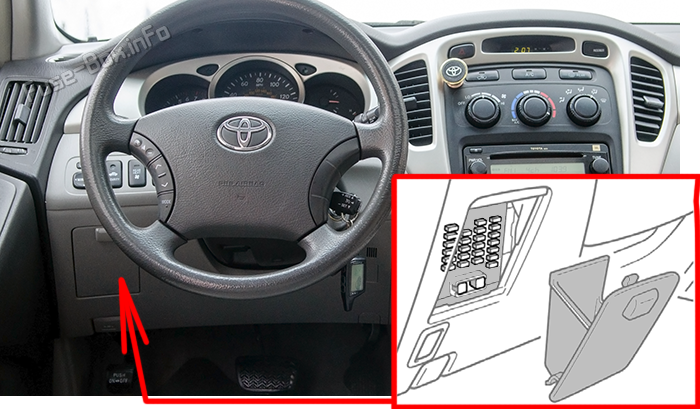
Fuse Box Diagram
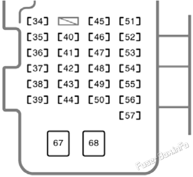
| № | Name | Amp | Description |
|---|---|---|---|
| 34 | IGN | 10A | Meters and gauges, SRS airbag system, hybrid system, electronically controlled brake system, engine immobilizer system |
| 35 | RAD №2 | 7.5A | Audio system, rear seat entertainment system, navigation system, air conditioning system, multiplex communication system |
| 36 | CIG | 15A | Cigarette lighter |
| 37 | P RR DOOR | 20A | Power windows |
| 38 | PWR OUTLET1 | 15A | Power outlets (12V DC) |
| 39 | FR FOG | 20A | Front fog lights |
| 40 | ECU-IG | 10A | Electronically controlled brake system, transmission control system, electric power steering system, theft deterrent system |
| 41 | WIPER | 25A | Windshield wipers |
| 42 | D RR DOOR | 20A | Power windows |
| 43 | D FR DOOR | 25A | Power windows, power door lock system, door courtesy light |
| 44 | S/ROOF | 20A | Electric moonroof |
| 45 | HEATER | 10A | Air conditioning system, rear heater system, rear window defogger, hybrid system |
| 46 | IG1 | 7.5A | Hybrid system, power door lock system, multiplex communication system, airbag on-off indicator lights, turn signal lights, back-up lights, outside rear view mirror defoggers, auto anti-glare inside rear view mirror, power outlet (115 VAC), seat heaters, navigation system |
| 47 | RR WIP | 15A | Rear window wiper |
| 48 | STOP | 20A | Stop lights, high mounted stoplight, electronically controlled brake system, transmission control system, hybrid system |
| 49 | OBD | 7.5A | On-board diagnosis system |
| 50 | SEAT HTR | 15A | Seat heaters |
| 51 | IG2 | 15A | Multiport fuel injection system/sequential fuel injection system, engine ignition system |
| 52 | WASHER | 20A | Windshield washer, rear window washer |
| 53 | FUEL OPN | 7.5A | Fuel filler door opening system |
| 54 | FR DEF | 20A | Windshield wiper deicer, rear view mirror defoggers |
| 55 | P FR DOOR | 20A | Power windows, door courtesy light |
| 56 | TAIL | 10A | Parking lights, tail lights, side marker lights, license plate lights, front fog lights |
| 57 | PANEL | 7.5A | Instrument panel lights |
| 67 | AM1 | 40A | Fuses: “ECU-IG”, “WASHER”, “IG1”, “WIPER”, “RR WIP”, “HEATER (10 A)”, “RAD №2” and “CIG” |
| 68 | POWER | 30A | Power seat |
Advertisements
Engine Compartment Fuse Boxes
Engine Compartment Fuse Boxes
Fuse Box Location
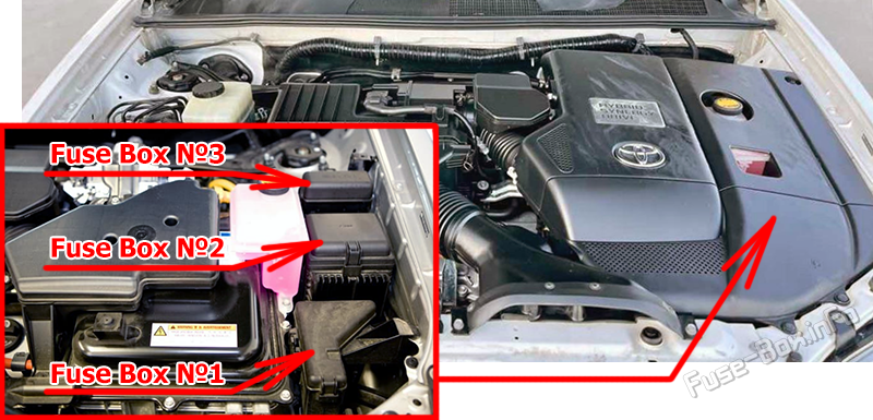
Fuse Box №1 Diagram
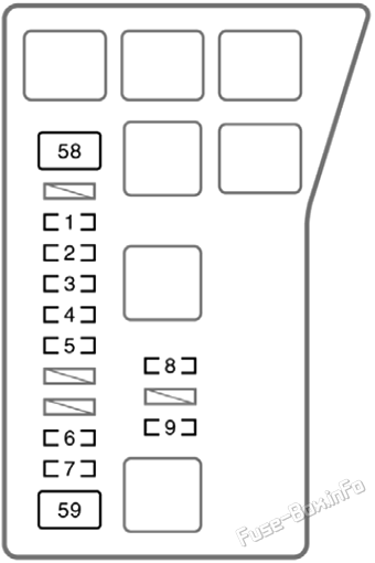
| № | Name | Amp | Description |
|---|---|---|---|
| 1 | ETCS | 10A | Hybrid system |
| 2 | DC/DC-S | 10A | Hybrid system |
| 3 | ABS №2 | 10A | Electronically controlled brake system |
| 4 | ABS №1 | 10A | Electronically controlled brake system |
| 5 | BATT FAN | 15A | Hybrid system |
| 6 | ABS №3 | 15A | Electronically controlled brake system |
| 7 | OIL PUMP | 10A | Transmission fluid cooling system |
| 8 | ST | 7.5A | Hybrid system |
| 9 | RR HTR | 15A | Rear heater system |
| 58 | ABS MTR2 | 30A | Electronically controlled brake system |
| 59 | ABS MTR1 | 30A | Electronically controlled brake system |
Fuse Box №2 Diagram
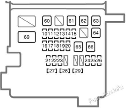
| № | Name | Amp | Description |
|---|---|---|---|
| 10 | DRL | 7.5A | Daytime running light system |
| 11 | H-LP L LWR | 15A | Left-hand headlight (low beam) |
| 12 | H-LP L UPR | 15A | Left-hand headlight (high beam) |
| 13 | H-LP R UPR | 15A | Right-hand headlight (high beam) |
| 14 | PWR OUTLET №2 | 20A | Power outlet (115V AC) |
| 15 | TOWING | 20A | Trailer lights |
| 16 | HAZ | 15A | Turn signal lights, emergency flashers |
| 17 | SECURITY | 15A | Theft deterrent system |
| 18 | AM2 №1 | 30A | Fuses: “IGN”, “IG2” and “ST” |
| 19 | MPX-B1 | 7.5A | Electric power steering system |
| 20 | HORN | 10A | Horns |
| 21 | RADIO №1 | 25A | Audio system |
| 22 | ECU-B №1 | 7.5A | Theft deterrent system, air conditioning system, gauges and meters, electric moonroof, engine immobilizer system, multiplex communication system |
| 23 | DOME | 10A | Personal lights, interior lights, vanity lights, ignition switch light, wireless remote control system, gauges and meters, navigation system |
| 24 | DOOR №1 | 25A | Power door lock system |
| 25 | A/F | 25A | Air/fuel control system |
| 26 | CRT | 7.5A | Rear seat entertainment system, navigation system screen |
| 27 | H-LP R LWR | 15A | Right-hand headlight (low beam) |
| 28 | INV W/P | 15A | Hybrid system |
| 29 | IGCT №5 | 10A | Hybrid system |
| 60 | HEATER | 50A | Air conditioning system, “WATER PUMP” fuse |
| 61 | RR HTR | 30A | Rear heater system |
| 62 | RR DEF | 30A | Rear window defogger |
| 63 | RDI FAN №1 | 40A | Electric cooling fan |
| 64 | RDI FAN №2 | 40A | Electric cooling fan |
| 65 | MAIN | 40A | Fuses: “H-LP L LWR”, “H-LP L UPR”, “H-LP R LWR”, “H-LP R UPR” and “DRL” |
| 66 | IGCT №1 | 50A | Fuses: “INV W/P”, “IGCT №2”, “IGCT №3”, “IGCT №4” and “IGCT №5” |
| 69 | DC/DC | 120A | Hybrid system |
Fuse Box №3 Diagram
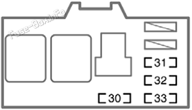
| № | Name | Amp | Description |
|---|---|---|---|
| 30 | WATER PUMP | 10A | Air conditioning system |
| 31 | IGCT №4 | 10A | Emission control system, transmission control system, air/fuel control system |
| 32 | IGCT №3 | 10A | Hybrid system, fuel pump |
| 33 | IGCT №2 | 10A | Hybrid system |
Advertisements


 How to check the fuses?
 How to replace a blown fuse?
 Why do car fuses blow?
 Types of automotive fuses