Advertisements
See other Toyota Land Cruiser 70:
Fuse Layout Toyota Land Cruiser 70 2009-2014
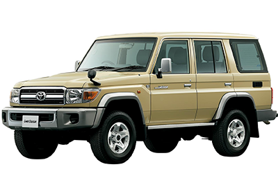
Table of Contents
Passenger Compartment Fuse Box
Passenger Compartment Fuse Box
Fuse Box Location
Remove the lid to access.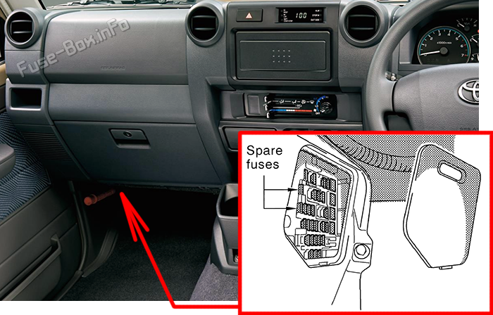
Fuse Box Diagram
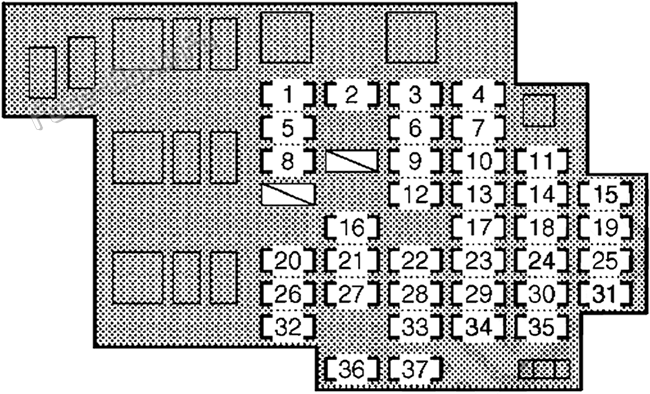
| № | Name | Amp | Description |
|---|---|---|---|
| 1 | DIFF | 30A | Differential lock system |
| 2 | DOOR | 30A | Power door lock system / wireless remote control system |
| 3 | POWER | 30A | Power windows |
| 4 | TRAILER | 30A | Trailer lights (tail lights), turn signal lights |
| 5 | ECU IG | 15A | 2009-2012: Electronically controlled fuel injection pump system, charging system, engine glow system, four-wheel drive control system, windshield wipers and washer, power antenna, differential lock system 2012-2014: Electronically controlled fuel injection pump system, charging system, engine glow system, four-wheel drive control system, windshield wipers and washer, power antenna, differential lock system, ABS, wireless remote control system |
| 6 | WIP | 20A | Windshield wipers and washer |
| 7 | CIG | 15A | Cigarette lighter |
| 8 | GAUGE | 15A | Back-up lights, air conditioning system, rear window defogger, electronically controlled fuel injection pump system, clock, emergency flashers |
| 9 | FUEL HTR | 15A | Fuel heater |
| 10 | ACC | 7.5A | Clock, audio system, power antenna |
| 11 | STOP | 15A | Electronically controlled fuel injection pump system, stop lights, high mounted stoplight |
| 12 | DC/DC | 15A | DC/DC converter |
| 13 | H/LP HI LH | 10A | No circuit |
| 14 | TRAILER STOP | 15A | Trailer lights (tail lights) |
| 15 | PANEL | 10A | Clock, audio system, emergency flashers, instrument panel light control, door lock system, rear window defogger, power antenna, gauges and meters, air conditioning system |
| 16 | DOME №1 | 10A | 2009-2012: Gauges and meters, interior light 2012-2014: Gauges and meters, interior light, wireless remote control system |
| 17 | H/LP HI RH | 10A | Right-hand headlight (high beam), service reminder indicators and warning buzzers |
| 18 | OBD2 | 7.5A | On-board diagnosis system |
| 19 | TAIL | 10A | Parking lights, tail lights, license plate lights, electronically controlled fuel injection pump system, trailer lights (tail lights) |
| 20 | FR FOG | 15A | Front fog lights, gauges and meters |
| 21 | ECU-B | 10A | Electronically controlled fuel injection pump system, clock, power antenna |
| 22 | INJ | 10A | Electronically controlled fuel injection pump system |
| 23 | H/LP LO LH | 10A | Left-hand headlight (low beam) |
| 24 | STOP | 30A | All components in “STOP” and “TRAILER STOP” fuses |
| 25 | DOME №2 | 10A | Interior lights |
| 26 | RR FOG | 15A | No circuit |
| 27 | RADIO | 15A | Audio system |
| 28 | IGN | 10A | Electronically controlled fuel injection pump system, SRS airbag system |
| 29 | H/LP LO RH | 10A | Right-hand headlight (low beam) |
| 30 | DEFOG | 20A | Electronically controlled fuel injection pump system, rear window defogger |
| 31 | EFI №2 | 10A | Electronically controlled fuel injection pump system |
| 32 | A/C | 10A | Air conditioning system |
| 33 | MET | 10A | Gauges and meters |
| 34 | ST | 7.5A | Electronically controlled fuel injection pump system, starting system, engine glow system |
| 35 | BLACK | 7.5A | No circuit |
| 36 | SPARE | 10A | Spare fuse |
| 37 | SPARE | 20A | Spare fuse |
Advertisements
Engine Compartment Fuse Boxes
Engine Compartment Fuse Boxes
Fuse Box Location
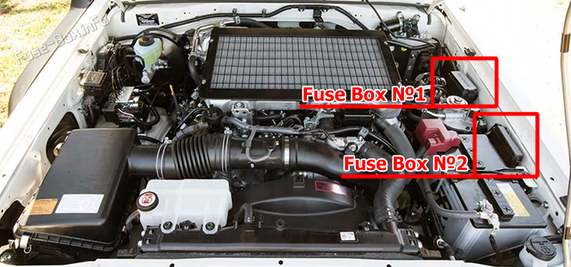
Fuse Box №1 Diagram
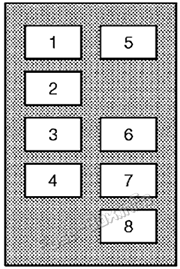
| № | Name | Amp | Description |
|---|---|---|---|
| 1 | HTR | 50A | Air conditioning system |
| 2 | ALT | 140A | All components in “GLOW1”, “GLOW2”, “HEAD”, “MAIN1 ”, “MAIN2”, “AM2”, “HORN”, “EFI MAIN”, “EFI MAIN2”, “TURN&HAZ”, “ALT-S”, “H/LP LO RH”, “H/LP LO LH”, “TRAILER”, “H/LP HI RH”, “TAIL”, “PANEL”, “FR FOG”, “DOME”, “ECU-B”, “RADIO” and “DOOR” fuses |
| 3 | GLOW1 | 80A | Engine glow system |
| 4 | GLOW2 | 80A | Engine glow system |
| 5 | AM1 №2 | 50A | 2009-2012: All components in “ECU IG”, “GAUGE” and “WIP" fuses 2012-2014: All components in “ECU IG”, “GAUGE” and “WIP" fuses, front fog lights, rear fog lights |
| 6 | AM1 | 30A | Cigarette lighter, starting system, all components in “ST” and “ACC” fuses |
| 7 | AM1 №3 | 50A | Cigarette lighter, all components in “ACC” fuse |
| 8 | ALT MAIN | 50A | Stop lights, air conditioning system, on-board diagnosis system, audio system |
Fuse Box №2 Diagram

| № | Name | Amp | Description |
|---|---|---|---|
| 1 | HEAD | 50A | Right-hand headlight (low beam), left-hand headlight (low beam), right-hand headlight (high beam), left-hand headlight (high beam) |
| 2 | MAIN2 | 50A | 2009-2012: Audio system, all components in “ECU-B”, “DOME №1”, “DOME №2” and “DOOR” fuses |
| ABS MTR | 50A | 2012-2014: ABS | |
| 3 | MAIN1 | 50A | 2009-2012: Tail lights, front fog lights, rear fog lights, all components in “PANEL” fuse 2012-2014: Tail lights, all components in “PANEL” fuse, trailer, audio system, all components in “ECU-B”, “DOME №1” and “DOOR” fuses |
| 4 | AM2 | 50A | All components in “MET”, “IGN” and “INJ” fuses |
| 5 | HORN | 10A | Horns |
| 6 | EFI MAIN | 15A | Electronically controlled fuel injection pump system |
| 7 | EFI MAIN2 | 15A | Electronically controlled fuel injection pump system |
| 8 | TURN&HAZ | 15A | Turn signal lights, tail lights, service reminder indicators and warning buzzers, trailer lights (tail lights) |
| 9 | ABS SOL | 30A | 2012-2014: ABS |
| 10 | ALT-S | 7.5A | Charging system |
Advertisements


 How to check the fuses?
 How to replace a blown fuse?
 Why do car fuses blow?
 Types of automotive fuses