
Advertisements
Fuse Layout VW ID.4 & VW ID.5

Table of Contents
Passenger Compartment Fuse Box (Fuse Panel C -SC-)
Passenger Compartment Fuse Box (Fuse Panel C -SC-)
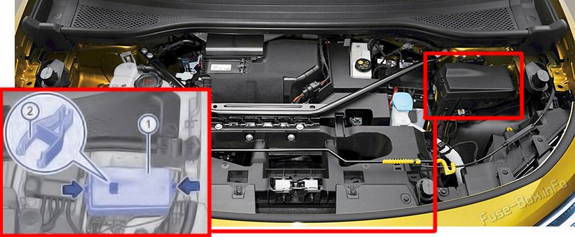
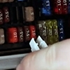
Fuse Box Location
Left-hand drive vehicle: Reach behind the cover and pull off in the direction of the arrow.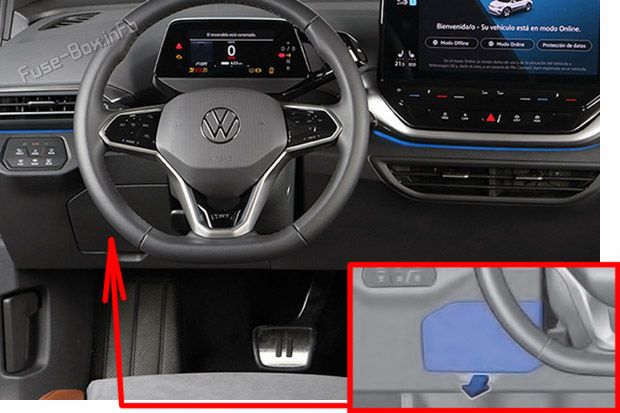
Right-hand drive vehicle: Open the glove box and empty if necessary; reach behind the cover from the side and pull it backwards (2).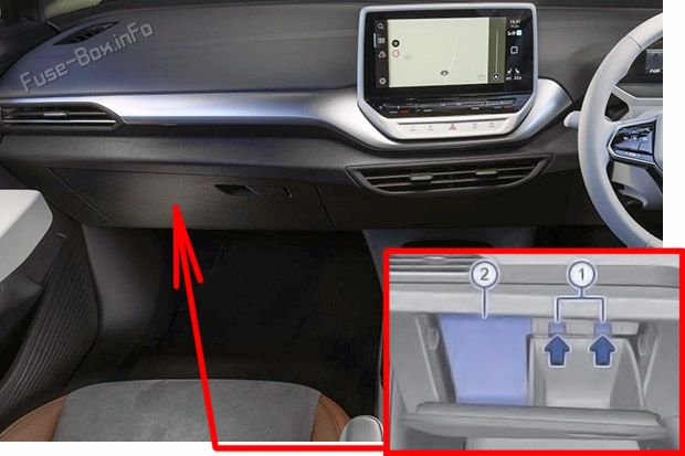
Fuse Box Diagram
| № | Amps | Function / component |
|---|---|---|
| SC1 | - | - |
| SC2 | 15A | Airbag control unit |
| SC3 | 25A | Trailer detector control unit |
| SC4 | 7.5A | Front camera for driver assist systems |
| SC5 | 25A | Onboard supply control unit (left exterior lighting) |
| SC6 | 30A | Onboard supply control unit (interior lighting) |
| SC7 | 30A | Heater and air conditioning system control unit (seat heating) |
| SC8 | 15A | Sliding sunroof adjustment control unit |
| SC9 | 30A | Driver door control unit (For left-hand drive models) Front passenger door control unit For right-hand drive models) Rear driver side door control unit (For left-hand drive models) Passenger side rear door control unit For right-hand drive models) |
| SC10 | 10A | Left tail light cluster Centre tail light cluster |
| SC11 | 15A | Trailer detector control unit |
| SC12 | - | - |
| SC13 | 40 A | Onboard supply control unit (central locking) |
| SC14 | 30A | Digital sound package control unit |
| SC15 | - | - |
| SC16 | - | - |
| SC17 | 5A | Parking aid control unit Lane change assist control unit Lane change assist control unit 2 |
| SC18 | 5A | Control unit for electronic steering column lock Rear lid power opening control unit Interface for entry and start system Control unit 2 for break-in protection Control unit 3 for break-in protection Control unit 4 for break-in protection Control unit 5 for break-in protection Control unit for mobile-controlled entry and start authorisation system Engine sound generator module 2 |
| SC19 | 5A | Emergency call module control unit and communication unit Control unit with display unit for driver information system |
| SC20 | 7.5A/10A | Telephone bracket Transmission and reception stabilisation control unit USB connection 1 |
| SC21 | 7.5A | Rear lid handle Control unit for overhead view camera |
| SC22 | 10A | Engine/motor control unit |
| SC23 | 5A | Internet access control unit |
| SC24 | 10A | Right tail light cluster Centre tail light cluster |
| SC25 | 25A | Front left seat belt |
| SC26 | 30A | Driver door control unit (For right-hand drive models) Front passenger door control unit (For left-hand drive models) Rear driver side door control unit For right-hand drive models) Passenger side rear door control unit (For left-hand drive models) |
| SC27 | 25A | Front right seat belt |
| SC28 | 10A | Battery regulation control unit Maintenance connector for high-voltage system |
| SC29 | 15A | Trailer detector control unit |
| SC30 | 25A/20A | Control unit 1 for information electronics |
| SC31 | 25A | Trailer detector control unit |
| SC32 | 25A | Onboard supply control unit (right exterior lighting) |
| SC33 | - | - |
| SC34 | 15A | Heater and air conditioning system control unit |
| SC35 | - | - |
| SC36 | 40A | Fresh air blower control unit |
| SC37 | 30A | Rear lid control unit |
| SC38 | 7.5A | Control unit for front left massage seat Control unit for front right massage seat |
| SC39 | 15A | Steering column electronics control unit |
| SC40 | 7.5A/10A | Alarm horn |
| SC41 | 5A | Data bus diagnostic interface |
| SC42 | - | - |
| SC43 | 7.5A | Operating and display unit for rear air conditioning system Sensor for interior carbon dioxide concentration Vehicle interior temperature sensor Heated rear window relay |
| SC44 | 7.5A | Operating unit for window regulator in driver door Diagnostic connection Light switch (dipped beam) Rain and light sensor, Background lighting ID. Light |
| SC45 | 5A | Steering column electronics control unit |
| SC46 | 7.5A/10A | Display unit for front information display and operating unit control unit Control unit for Head-up Display |
| SC47 | 10A | Electronically controlled damping control unit |
| SC48 | 7.5A/10A | USB charging socket 1 |
| SC49 | - | - |
| SC50 | - | - |
| SC51 | - | - |
| SC52 | 20A | 12 V socket 3 |
| SC53 | - | - |
| SC54 | - | - |
| SC55 | - | - |
| SC56 | - | - |
| SC57 | - | - |
| SC58 | 7.5A | Control unit for mobile-controlled entry and start authorisation system |
| SC59 | 7.5A | Seat occupied recognition control unit Relay for power sockets Automatic anti-dazzle interior mirror |
| SC60 | 7.5A | Diagnostic connection |
| SC61 | 5A | Power and control electronics for electric drive Power and control electronics 2 for electric drive |
| SC62 | - | - |
| SC63 | - | - |
| SC64 | - | - |
| SC65 | - | - |
| SC66 | 15A | Rear window wiper motor |
| SC67 | 30A | Frequency modulation (FM) frequency filter in positive wire Rear window heating |
| R1 | Relay for power sockets | |
| R2 | Terminal 15 voltage supply relay | |
| R3 | Heated rear window relay |
Individual fuses
| № | Amps | Function / component |
|---|---|---|
| A | 30A | Potentiometer for electric trailer brakes (For American markets) |
| B | - | - |
| C | 15A | Driver seat adjustment control unit |
| D | 15A | Front passenger seat adjustment control unit |
Advertisements
Front Compartment Fuse Box
Front Compartment Fuse Box
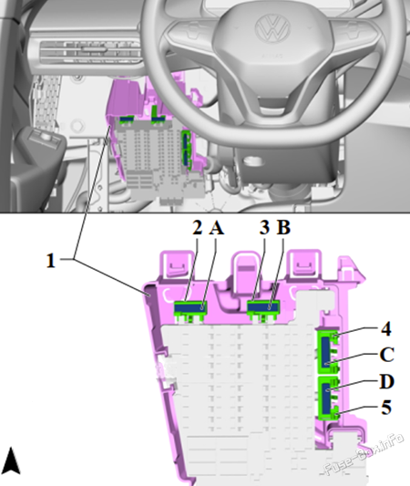
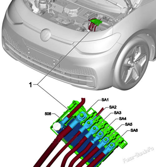
Fuse Box Location
- Open the bonnet;
- Press the locking button in the direction of the arrow (arrows) in order to unlock the cover of the fuse box (1);
- Lift off the cover.
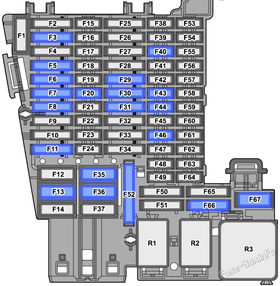
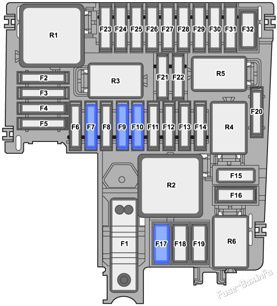
Fuse Box Diagram (Fuse panel B -SB-)
| № | Amps | Function / component |
|---|---|---|
| F1 | - | - |
| F2 | 7.5A | ABS control unit |
| F3 | 10A | Charging unit 1 for high-voltage battery Power and control electronics for electric drive Power and control electronics 2 for electric drive |
| F4 | 30A | Front left headlight |
| F5 | 30A | Front right headlight |
| F6 | 7.5A | Adaptive cruise control unit |
| F7 | 30A | Front wipers, right |
| F8 | - | - |
| F9 | 15A | Onboard supply control unit (horn) |
| F10 | 30A | Wiper motor control unit Front wipers, left |
| F11 | 7.5A | Air conditioning system relay |
| F12 | 7.5A | Engine sound generator module 1 |
| F13 | 25A | ABS control unit |
| F14 | - | - |
| F15 | 40A | ABS control unit |
| F16 | 50A | Radiator fan |
| F17 | 40A | Heated windscreen |
| F18 | - | - |
| F19 | - | - |
| F20 | - | - |
| F21 | - | - |
| F22 | - | - |
| F23 | 10A | Engine/motor control unit |
| F24 | 5A | Radiator fan |
| F25 | 10A | Coolant pump for high-voltage battery PTC heater element 3 |
| F26 | 10A | Coolant pump for low-temperature circuit Control motor for radiator roller blind |
| F27 | - | - |
| F28 | - | - |
| F29 | - | - |
| F30 | - | - |
| F31 | - | - |
| F32 | 50A | Brake servo |
| R1 | Main relay | |
| R2 | Heated windscreen relay | |
| R3 | Horn relay | |
| R4 | - | |
| R5 | - | |
| R6 | Air conditioning system relay |
High power fuses (Fuse panel A -SA-)
| № | Amps | Function / component |
|---|---|---|
| 508 | - | Battery |
| SA1 | 350A | Voltage converter |
| SA2 | 80A | Battery monitor control unit Power steering control unit |
| SA3 | 100A | Fuse holder C |
| SA4 | 100A | Fuse holder C |
| SA5 | - | - |
| SA6 | 125A | Fuse holder B |
Advertisements