
Advertisements


Fuse Layout Ford F150 Lightning

Table of Contents
Passenger Compartment Fuse Box
Passenger Compartment Fuse Box
Fuse Box Location
The fuse panel is in the right-hand side of the passenger footwell behind a trim panel.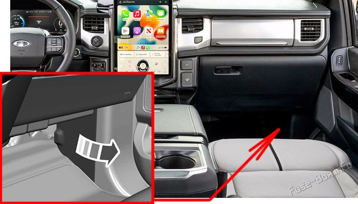
Fuse Box Diagram
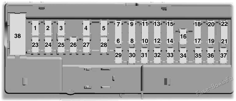
| № | Amps | Protected Component |
|---|---|---|
| 1 | - | Not used. |
| 2 | 10A | Driver window switch-delayed accessory feed. Moonroof. Sliding backglass switch. |
| 3 | 7.5A | Wireless accessory charging module. |
| 4 | 20A | Not used (spare). |
| 5 | - | Not used. |
| 6 | 10A | Driver window switch-powered at all times. |
| 7 | 10A | Gearshift module. |
| 8 | 5A | Telematics control module. Power tailgate control module. |
| 9 | 5A | Inclination sensor. |
| 10 | - | Not used. |
| 11 | - | Not used. |
| 12 | 7.5A | Climate control module. |
| 13 | 7.5A | Instrument cluster. Steering column control module. |
| 14 | 15A | Frunk module. |
| 15 | 15A | Integrated control module. Accessory protocol interface module. |
| 16 | - | Not used. |
| 17 | 7.5A | Not used (spare). |
| 18 | 7.5A | Not used (spare). |
| 19 | 5A | Headlamp switch. Bluetooth low energy module. |
| 20 | 5A | Start switch. |
| 21 | 5A | Trailer brake switch. |
| 22 | 5A | Not used (spare). |
| 23 | 30A | Driver door control module. |
| 24 | 30A | Moonroof. Sunshade module. |
| 25 | 20A | Not used (spare). |
| 26 | 30A | Passenger door control module. |
| 27 | 30A | Not used (spare). |
| 28 | 30A | Amplifier. |
| 29 | 15A | Adjustable pedal switch. 12"/15" display. |
| 30 | 5A | Not used (spare). |
| 31 | 10A | Driver status monitor. Radio transceiver module. |
| 32 | 20A | Radio. Enhanced central gateway. |
| 33 | - | Not used. |
| 34 | 30A | Run/start relay. |
| 35 | 5A | Not used (spare). |
| 36 | 15A | Rear heated seat module. Steering column control module. Auto-dimming mirror. |
| 37 | 20A | Not used (spare). |
| 38 | 30A CB | Rear window switches. |
Advertisements
Front Compartment Fuse Box
Front Compartment Fuse Box
Fuse Box Location
To access, first remove the right-side frunk cover then remove the fuse box cover: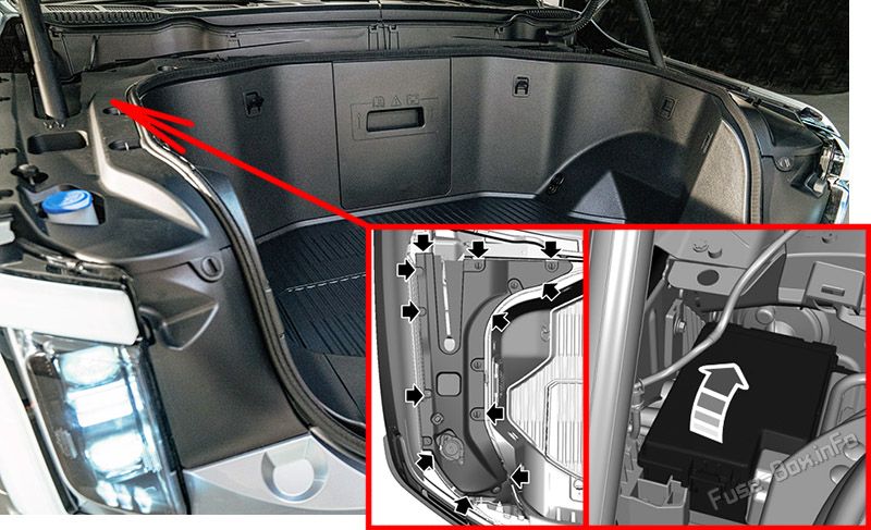
- Start at the rear edge of the right hand-side and work toward the front of the cover.
- Pull upward at the clip locations shown to release the clips.
- Remove the frunk cover.
- Remove the top cover.
Fuse Box Diagram
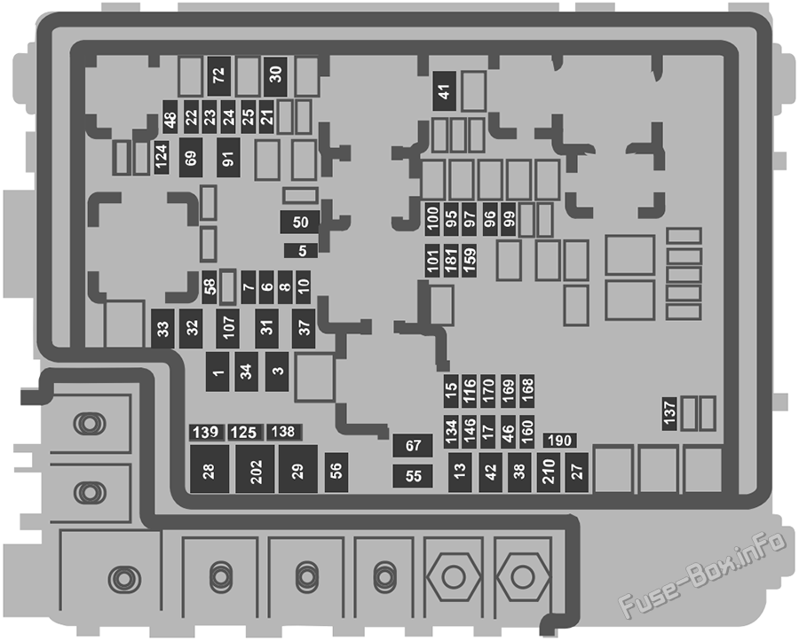
| № | Amps | Protected Component |
|---|---|---|
| 1 | 40A | Body control module. |
| 3 | 40A | Body control module. |
| 5 | 5A | Primary drive control module. Secondary drive control module. |
| 6 | 25A | Powertrain control module. |
| 7 | 20A | Powertrain control module heater cooling pump. |
| 8 | 20A | A/C control module. Active grille shutter. Front bumper valance motor. Electric fan relay coil. |
| 10 | 10A | Auxiliary power point. |
| 13 | 40A | Blower motor. |
| 15 | 25A | Horn. |
| 17 | 5A | Charge port status indicator. |
| 21 | 10A | Not used (spare). |
| 22 | 10A | Electronic power assist steering module. |
| 23 | 10A | Anti-lock brake system module. |
| 24 | 10A | Primary drive control module. Secondary drive control module. Powertrain control module. |
| 25 | 10A | Trailer camera module. Trailer tire pressure monitoring system. Trailer sway control. |
| 27 | 25A | Primary drive control module fluid pump. |
| 28 | 50A | Anti-lock brake system module. |
| 29 | 50A | Anti-lock brake system module. |
| 30 | 40A | Driver seat module. |
| 31 | 30A | Passenger power seat. |
| 32 | 20A | Power point. |
| 33 | 20A | Not used (spare). |
| 34 | 20A | Auxiliary power point. |
| 37 | 30A | Power tailgate module. |
| 38 | 40A | Climate control module. |
| 41 | 25A | Heated rear window. |
| 42 | 30A | Trailer brake control module. |
| 46 | 10A | Battery charger control module. |
| 48 | 20A | Rear heated seat module. |
| 50 | 40A | Heated backlite. |
| 55 | 30A | Trailer tow park lamps. |
| 56 | 20A | Trailer tow stoplamps. |
| 58 | 10A | Trailer tow backup lamps. |
| 67 | 25A | Secondary drive control module fluid pump. |
| 69 | 30A | Front wiper motor. |
| 72 | 40A | Front trunk module. |
| 91 | 20A | Trailer tow lighting module. |
| 95 | 15A | Primary drive control module. |
| 96 | 20A | Coolant pump. |
| 97 | 10A | A/C pressure and temperature sensor. High voltage battery cooling module. |
| 99 | 15A | Secondary drive control module. High voltage positive temperature coefficient heater. |
| 100 | 25A | Left-hand headlamp. |
| 101 | 25A | Right-hand headlamp. |
| 107 | 30A | Trailer tow lighting module. |
| 116 | 10A | Second battery charger control module. |
| 124 | 5A | Rain sensor. |
| 125 | 10A | USB smart charger 1. USB smart charger 2. |
| 134 | 25A | Driver multi-contour seat. Passenger multi-contour seat. |
| 137 | 20A | Advanced driver assistance system module. High mounted stoplamp rear video camera. |
| 138 | 10A | Tailgate release solenoid. |
| 139 | 5A | USB smart charger 3. |
| 146 | 15A | Battery energy control module. |
| 159 | 5A | Direct current/direct current converter. |
| 160 | 10A | Smart datalink connector. |
| 168 | 15A | Battery energy control module. Pedestrian sounder. |
| 169 | 20A | Coolant pump. |
| 170 | 20A | High voltage battery coolant pump. |
| 181 | 5A | Headlamp control module. |
| 190 | 5A | Not used (spare). |
| 202 | 60A | Body control module. |
| 210 | 30A | Body control module. |
Advertisements