
Advertisements
See other Mercedes-Benz M-Class:

Fuse Layout Mercedes-Benz M-Class / ML-Class 2006-2011

Cigar lighter (power outlet) fuses in the Mercedes-Benz M-Class are the fuses #44, #45 and #46 in the Luggage Compartment Fuse Box.
Table of Contents
Instrument Panel Fuse Box
Instrument Panel Fuse Box
Fuse box location
The fuse box is located on the passenger side edge of the instrument panel, behind the cover.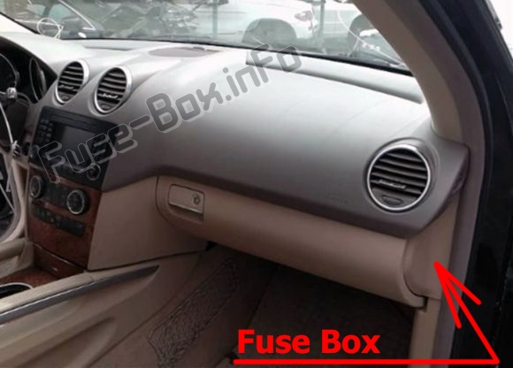
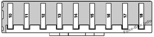
Fuse box diagram
| № | Description | Amp |
|---|---|---|
| 10 | Booster blower electronic blower controller | 10 |
| 11 | Instrument cluster | 5 |
| 12 | AAC [KLA] control and operating unit Comfort AAC [KLA] control and operating unit | 15 |
| 13 | Steering column module Upper control panel control unit | 5 |
| 14 | EIS [EZS] control unit | 7.5 |
| 15 | Electronic compass Media interface control unit | 5 |
| 16 | Spare | - |
| 17 | Spare | - |
| 18 | Spare | - |
Advertisements
Battery compartment pre-fuse box
Battery compartment pre-fuse box
The battery compartment prefuse box is located next to battery under the front passenger seat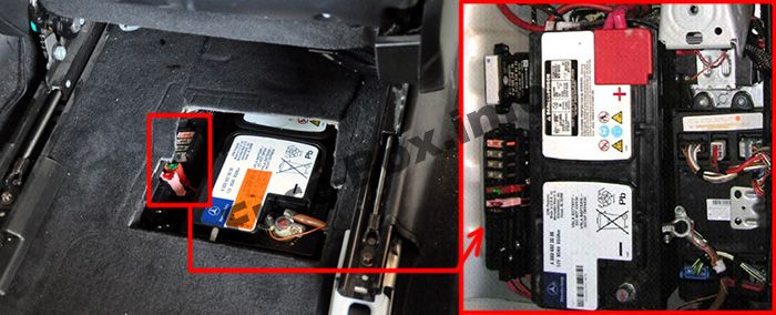
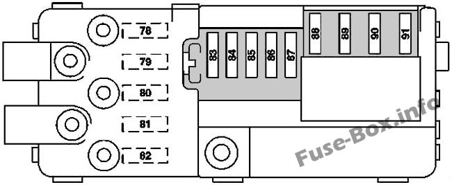
| № | Description | Amp |
|---|---|---|
| 78 | up to 30.6.09: PTC heater booster | 100 |
| 78 | up to 2008; as of 1.7.09: PTC heater booster | 150 |
| 79 | Rear SAM control unit | 60 |
| 80 | Rear SAM control unit | 60 |
| 81 | Valid for engine 642.820: AdBlue relay supply | 40 |
| 81 | Valid as of 1.7.09 without engine 642.820: Engine compartment fuse and relay box Valid for model 164.195: Vacuum pump relay (+) Up to 2008: - | 150 |
| 82 | Load compartment fuse and relay box | 100 |
| 83 | Weight Sensing System (WSS) control unit | 5 |
| 84 | Restraint systems control unit | 10 |
| 85 | As of 2009: DC/AC converter control unit (115 V socket) | 25 |
| 85 | Up to 2008: Intelligent servo module for DIRECT SELECT | 30 |
| 86 | Cockpit fuse box | 30 |
| 87 | Transfer case control unit | 30 |
| 87 | Valid for model 164.195:Fuse and relay box 2, engine compartment | 15 |
| 88 | Front SAM control unit | 70 |
| 89 | Front SAM control unit | 70 |
| 90 | Front SAM control unit | 70 |
| 91 | As of 2009: AC air recirculation unit Up to 2008: Blower regulator | 40 |
Engine Compartment Fuse Box
Engine Compartment Fuse Box
Fuse box location
The fuse box is located in the engine compartment (right-side), under the cover.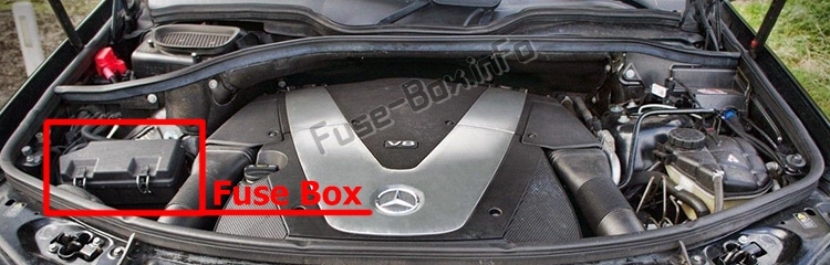
Fuse box diagram

Advertisements
Assignment of the fuses and relay in the engine compartment
| № | Description | Amp |
|---|---|---|
| 100 | Wiper motor | 30 |
| 101 | AAC with integrated control additional fan motor Valid for engine 156: Terminal 87 M3e connector sleeve Valid for engine 156, 272, 273: Purge control valve Valid for engines 272, 273: Circuit 87 M1e connector sleeve Suction-type fan control unit Valid for engine 629: CDI control unit Circuit 30 connector sleeve Suction fan control unit Valid for model 164.195: ME-SFI [ME] control unit Engine compartment/engine connector Valid for engine 642 except 642.820: CDI control unit O2 sensor upstream of CAT Suction fan control unit Valid for engine 642.820: O2 sensor upstream of CAT | 15 |
| 102 | Valid for engine 642.820 up to 31.7.10: Recirculation pump for transmission oil cooler Valid for engine 156: Engine coolant circulation pump | 15 |
| 102 | Valid for model 164.195: Recirculation pump for transmission oil cooler Low temperature coolant pump | 10 |
| 103 | Circuit 87 M1e connector sleeve CDI control unit Up to 2008; Valid for engines 113, 272, 273: ME-SFI [ME] control unit | 25 |
| 103 | Valid for model 164.195: ME-SFI [ME] control unit Valid for engine 272, 273:ME-SFI [ME] control unit | 20 |
| 104 | Valid for engine 156, 272, 273: Terminal 87M2e connector sleeve Valid for engine 629: Terminal 87 connector sleeve Valid for engine 642.820: Terminal 87 D2 connector sleeve Valid for engine 642 except 642.820: CDI control unit Valid for model 164.195: Interior and engine wiring harness connector Engine compartment fuse and relay box Valid for engine 113: ME control unit | 15 |
| 105 | Valid for engine 156, 272, 273: ME-SFI [ME] control unit Circuit 87 M1 i connector sleeve Valid for engine 629: CDI control unit Valid for engine 642.820: CDI control unit Fuel pump relay Valid for engine 642 except 642.820: CDI control unit Fuel pump relay (as of 2009) Starter (up to 2008) Valid for model 164.195: Interior and engine wiring harness connector Valid for engine 113: Circuit 15 connector sleeve, fused | 15 |
| 106 | Spare | - |
| 107 | Valid for engine 156, 272 and 273: Electric air pump Valid for model 164.195: Engine compartment/engine connector | 40 |
| 108 | AIRMATIC compressor unit | 40 |
| 109 | ESP control unit Valid for model 164.195: Regenerative braking system control unit | 25 |
| 110 | Alarm signal siren | 10 |
| 111 | Intelligent servo module for DIRECT SELECT | 30 |
| 112 | Left front lamp unit Right front lamp unit | 7.5 |
| 113 | Left fanfare horn Right fanfare horn | 15 |
| 114 | Up to 2008: - As of 2009: Front SAM control unit Valid for engine 629: CDI control unit | 5 |
| 115 | ESP control unit Valid for model 164.195: Regenerative braking system control unit | 5 |
| 116 | Electric controller unit (VGS) Valid for model 164.195: Hybrid vehicle fully integrated transmission control controller unit | 7.5 |
| 117 | DTR controller unit | 7.5 |
| 118 | Valid for engine 156, 272, 273: ME-SFI [ME] control unit Valid for engine 629, 642: CDI control unit | 5 |
| 119 | Valid for engine 642.820: CDI control unit | 5 |
| 120 | Valid for engine 156, 272, 273: ME-SFI [ME] control unit Engine circuit 87 relay Valid for engine 113: ME-SFI [ME] control unit Valid for engine 629: CDI control unit Valid for engine 629, 642: Engine circuit 87 relay | 10 |
| 121 | STH heater unit Valid for model 164.195: Fuse and relay box 2, engine compartment | 20 |
| 122 | Valid for engine 156, 272, 273, 629, 642: Starter Valid for engine 113, 272, 273: ME-SFI [ME] control unit | 25 |
| 123 | Valid for engine 642: Fuel filter condensation sensor with heating element Valid for engine 629, 642 as of 1.9.08: Fuel filter condensation sensor with heating element | 20 |
| 124 | Valid for model 164.120/122/822/825 as of 1.6.09, Model 164.121/124/125/824: Electrohydraulic power steering Valid for model 164.195: Electrohydraulic power steering Electric refrigerant compressor control unit | 7.5 |
| 125 | Valid for model 164.195: Power electronics control unit | 7.5 |
| Relay | ||
| A | Wiper level relay 1/2 | |
| B | Wiper ON / OFF | |
| C | Valid for engine 642: Additional circulation pump for transmission oil cooling Valid for engine 156: Engine coolant circulation pump | |
| D | Terminal 87 engine | |
| E | Secondary air injection pump | |
| F | Fanfare horn | |
| G | Air suspension compressor | |
| H | Circuit 15 | |
| I | Starter |
Advertisements
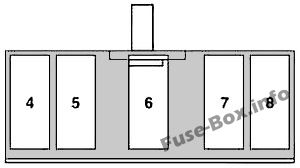
Front pre-fuse box
Front pre-fuse box
| № | Description | Amp |
|---|---|---|
| 4 | Spare | - |
| 5 | Valid for model 164.195 (ML 450 Hybrid): Regenerative braking system control unit | 40 |
| 6 | ESP control unit | 40 |
| 6 | Valid for model 164.195 (ML 450 Hybrid): Electrohydraulic power steering | 80 |
| 7 | AAC with integrated control additional fan motor | 100 |
| 8 | up to 2008: Engine compartment fuse and relay box | 140 |
| 8 | as of 2009: Engine compartment fuse and relay box | 100 |
Luggage Compartment Fuse Box
Luggage Compartment Fuse Box
Fuse box location
The fuse box is located in the luggage compartment (on the right-side), behind the cover.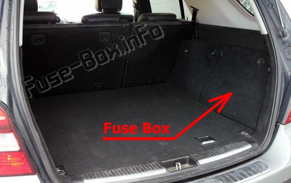
Fuse box diagram
Up to 31.05.2006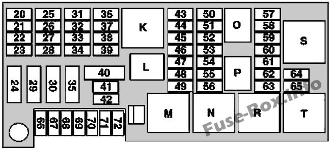
As of 01.06.2006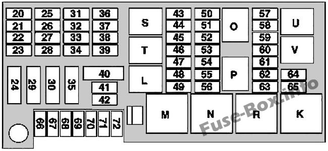
Advertisements
Assignment of the fuses and relay in the luggage compartment
| № | Description | Amp |
|---|---|---|
| 20 | Up to 2008: Roof antenna module As of 2009: Interference suppression filter for radio antenna As of 2009: Microphone array control unit (Japanese version) | 5 |
| 21 | RCP [HBF] control unit | 5 |
| 22 | PTS control unit STH radio remote control receiver | 5 |
| 23 | DVD player Rear audio control unit Portable CTEL separation point (Japanese version) E-net compensator Bluetooth module Universal Portable CTEL Interface (UPCI [UHI]) control unit (Japanese version) | 10 |
| 24 | Right front reversible emergency tensioning retractor | 40 |
| 25 | COMAND operating, display and control unit | 15 |
| 26 | Right front door control unit | 25 |
| 27 | Passenger-side front seat adjustment control unit with memory Front passenger seat adjustment comfort relay | 30 |
| 28 | Driver-side front seat adjustment control unit, with memory Driver seat adjustment comfort relay | 30 |
| 29 | Left front reversible emergency tensioning retractor | 40 |
| 30 | As of 2009: Folding rear bench seat control unit Valid for engine 156: Left fuel pump control unit Right fuel pump control unit Valid for model 164.195 (ML 450 Hybrid): Fuel pump control unit circuit 30 connector sleeve | 40 |
| 31 | HS [SIH], seat ventilation and steering wheel heater control unit | 10 |
| 32 | AIRmatic control unit | 15 |
| 33 | KEYLESS-GO control unit | 25 |
| 34 | Left front door control unit | 25 |
| 35 | Amplifier for sound system As of 2009: Subwoofer amplifier | 30 |
| 36 | Emergency call system control unit | 10 |
| 37 | Backup camera power supply module (Japanese version) Backup camera control unit (Japanese version) | 5 |
| 38 | Digital TV tuner Up to 2008: Audio gateway control unit (Japanese version) As of 2009: TV combination tuner (analog/digital) (Japanese version) Valid for model 164.195 (ML 450 Hybrid): High voltage battery module | 10 |
| 39 | Tire pressure monitor [RDK] control unit Up to 2008: SDAR control unit (USA version) As of 2009: High definition tuner control unit As of 2009: Digital Audio Broadcasting control unit As of 2009: External navigation separation point (South Korea version) | 7.5 |
| 40 | Up to 2008: Rear-end door closing control unit | 40 |
| 40 | As of 2009: Rear-end door closing control unit | 30 |
| 41 | Overhead control panel control unit | 25 |
| 42 | Up to 2008: SR motor As of 2009: Overhead control panel control unit | 25 |
| 43 | As of 2009; Valid for engine 272, 273: Fuel pump control unit Up to 31.05.2006: Tailgate wiper motor As of 01.06.2006: Not assigned | 20 |
| 44 | Up to 31.05.2006: Left 2nd seat row socket Up to 31.05.2006: Right 2nd seat row socket As of 01.06.2006: Not assigned As of 2009: Front interior socket (USA) As of 2009: 115V socket | 20 |
| 45 | Cargo area connector box Up to 2008: Front interior socket As of 2009: Right 2nd seat row socket | 20 |
| 46 | Front cigar lighter with ashtray illumination | 15 |
| 47 | Valid for model 164.195 (ML 450 Hybrid): High voltage battery coolant pump As of 2009: Left front illuminated door sill molding As of 2009: Right front illuminated door sill molding | 10 |
| 48 | As of 2009: Rear axle differential lock control unit As of 2009; Valid for engine 642.820: AdBlue® supply relay As of 1.7.09; Valid for model 164.195 or model 164.1 with engine 272 or model 164.8 with engine 642 or 273: Pyrotechnical separator | 5 |
| 49 | Heated rear window | 30 |
| 50 | Up to 31.05.2006: Tailgate wiper motor | 10 |
| 50 | As of 01.06.2006: Tailgate wiper motor | 15 |
| 51 | Activated charcoal canister shutoff valve | 5 |
| 52 | Up to 31.5.09: Left front reversible emergency tensioning retractor Up to 31.5.09: Right front reversible emergency tensioning retractor As of 2009: Rear axle differential lock control unit | 5 |
| 53 | AIRmatic control unit Valid for engine 156: Left fuel pump control unit Right fuel pump control unit Valid for engine 272, 273: Fuel pump control unit As of 2009: Transfer case control unit | 5 |
| 54 | Headlamp range adjustment control unit Front SAM control unit | 5 |
| 55 | Instrument cluster Rotary light switch | 7.5 |
| 56 | Up to 31.05.2006: Data link connector Valid for engine 642.820: AdBlue® control unit Valid for model 164.195: Fuel pump control unit | 5 |
| 57 | Up to 2008: Fuel pump with fuel gauge sensor Valid without engine 156: Fuel pump | 20 |
| 58 | Data link connector Central gateway control unit | 7.5 |
| 59 | As of 2009: Driver NECK-PRO head restraint solenoid As of 2009: Front passenger NECK-PRO head restraint solenoid | 7.5 |
| 60 | Glove compartment illumination with switch Engine compartment fuse and relay box Rear SAM control unit Cell phone separation point VICS+ETC voltage supply separation point (Japan version) Multicontour seat pneumatic pump (as of 2009) External navigation separation point (South Korea) Electrical connection, Blind-Spot-Monitoring interior rear bumper (as of 1.8.10) Emergency call system control unit (USA) | 5 |
| 61 | Up to 2008: Restraint systems control unit Right front seat contacting strip | 10 |
| 61 | As of 2009: Restraint systems control unit Right front seat contacting strip | 7.5 |
| 62 | Front passenger seat adjustment switch | 30 |
| 63 | Driver lumbar support regulator control unit Front passenger lumbar support regulator control unit Driver seat adjustment switch | 30 |
| 64 | Spare | - |
| 65 | Spare | - |
| 66 | As of 2009: Multicontour seat pneumatic pump | 30 |
| 67 | Rear air conditioning blower motor | 25 |
| 68 | Up to 2008: Left 2nd row seat heated cushion Up to 2008: Right 2nd row seat heated cushion As of 2009: HS [SIH], seat ventilation and steering wheel heater control unit | 25 |
| 69 | As of 2009: Rear axle differential lock control unit | 30 |
| 70 | Trailer hitch socket (13-pin) (as of 2009) Trailer hitch socket (7-pin) | 20 |
| 70 | Trailer hitch socket (13-pin) (up to 2008) | 15 |
| 71 | Electric brake control separation point | 30 |
| 72 | Trailer hitch socket (13-pin) | 15 |
| Relay | ||
| K | Up to 31.05.2006: Terminal 15R power outlet relay, with power-down As of 01.06.2006: Circuit 15R seat adjustment As of 2009: Relay, circuit 15R sockets (with K power-down) (power supply of electric seat adjustment) | |
| L | Terminal 30X | |
| M | Heated rear window relay | |
| N | Circuit 15 relay / terminal 87FW | |
| O | Fuel pump relay | |
| P | Rear wiper relay | |
| R | Circuit R relay 115R | |
| S | Reserve 1 (changer) (power supply for front socket) | |
| T | As of 01.06.2006Circuit 30, socket for 2nd seat row and load compartment As of 2009: Reserve 2 (normally open contact) (power supply for center and rear sockets) | |
| U | As of 01.06.2006Circuit 30, trailer | |
| V | As of 01.06.2006- |
AdBlue fuse block
AdBlue fuse block
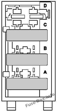
| № | Description | Amp |
|---|---|---|
| A | AdBlue control unit | 15 |
| B | AdBlue control unit | 20 |
| C | AdBlue control unit | 7.5 |
| D | Spare | - |
Advertisements