
Advertisements


Fuse Layout Toyota Sienna 2004-2010

Cigar lighter (power outlet) fuses in the Toyota Sienna are the fuses #3 “PWR OUTLET” (Power outlets), #4 “CIG” (Cigarette lighter) and #21 “AC INV” (Power outlets 115V) in the Instrument panel fuse box.
Table of Contents
Passenger Compartment Overview
Passenger Compartment Overview

Passenger Compartment Fuse Box
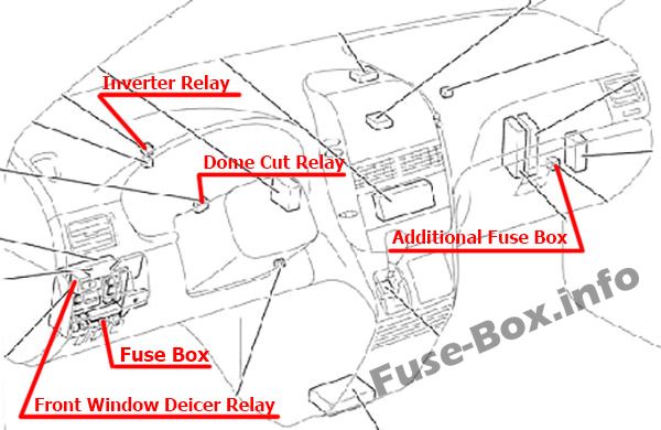
Fuse box location
The fuse box is located under the instrument panel (on the left side), behind the lid.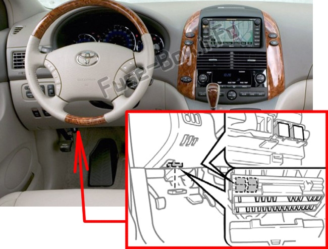
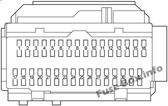
Fuse box diagram
Advertisements
Assignment of the fuses in the Passenger Compartment
| № | Name | Amp | Protected components |
|---|---|---|---|
| 1 | MIR HTR | 10 | Outside rear view mirror defoggers |
| 2 | RAD2 | 7.5 | Audio system, navigation system, rear seat entertainment system |
| 3 | PWR OUTLET | 15 | Power outlets |
| 4 | CIG | 15 | Cigarette lighter |
| 5 | ECU ACC | 7.5 | Shift lock control system, air conditioning system, power rear view mirror control |
| 6 | GAUGE2 | 7.5 | Meter and gauge |
| 7 | IGN | 7.5 | Multiport fuel injection system/ sequential multiport fuel injection system, SRS airbag system, multiplex communication system |
| 8 | INJ | 15 | 2003-2006: Multiport fuel injection system/ sequential multiport fuel injection system |
| 8 | IG2 | 7.5 | 2007-2010: Multiport fuel injection system/ sequential multiport fuel injection system |
| 9 | RR WIP | 15 | Rear window wiper |
| 10 | WIP | 30 | Windshield wiper and rear window wiper |
| 11 | GAUGE1 | 10 | Back-up lights, turn signal lights, emergency flashers |
| 12 | S-HTR | 15 | Seat heaters |
| 13 | WSH | 20 | Windshield washer and rear window washer |
| 14 | HTR | 10 | Air conditioning system |
| 15 | - | - | - |
| 16 | ECU-IG | 10 | Intuitive parking assist system, rear view monitor system, multiplex communication system, multiport fuel injection system/sequential multiport fuel injection system, antilock brake system, traction control system, vehicle stability control system, shift lock control system, dynAM1c laser cruise control system, seat heaters, power back door, moon roof, multi-information display, auto antiglare inside rear view mirror, power windows, power outlets (115 V), power third seat, driving position memory system |
| 17 | PANEL | 10 | Air conditioning system, seat heaters, audio system, navigation system, power sliding door, power back door, trip information display, rear window defogger, emergency flashers, instrument panel lights, steering switch lights |
| 18 | TAIL | 10 | Stop/tail lights, license plate lights, parking lights, side maker lights |
| 19 | S/ROOF | 25 | Moon roof |
| 20 | - | - | - |
| 21 | AC INV | 15 | Power outlets (115 V) |
| 22 | FR DEF | 15 | Windshield wiper de-icer |
| 23 | AM1 | 7.5 | Multiport fuel injection system/ sequential multiport fuel injection system, starter system |
| 24 | - | - | - |
| 25 | - | - | - |
| 26 | STOP | 10 | Stop/tail lights, high mounted stoplight, shift lock control system, antilock brake system, traction control system, vehicle stability control system, multiport fuel injection system/sequential multiport fuel injection system, multiplex communication system |
| 27 | P/W | 25 | Power windows, power rearview mirror |
| 28 | OBD | 7.5 | On-board diagnosis system |
| 29 | FOG | 15 | Front fog lights |
| 30 | - | - | - |
| 31 | - | - | - |
| 32 | P/VENT | 15 | Power quarter windows |
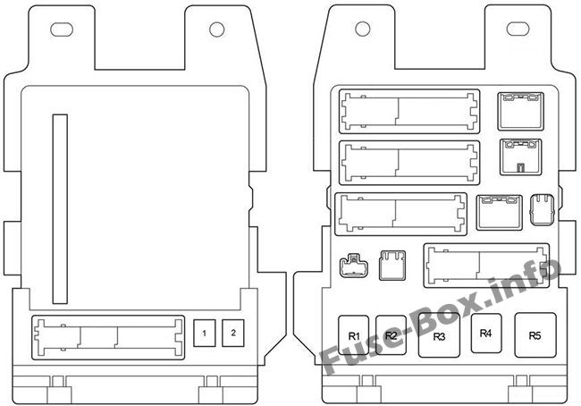
| № | Name | Amp | Circuit |
|---|---|---|---|
| 1 | P/SEAT | 30 | Power seats |
| 2 | POWER | 30 | Power windows |
| Relay | |||
| R1 | Fog Lights | ||
| R2 | Tail Lights | ||
| R3 | Accessory Relay (ACC) | ||
| R4 | Power Relay (PWR) | ||
| R5 | Ignition (IG1) |
Advertisements
Additional Fuse Box
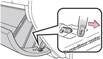
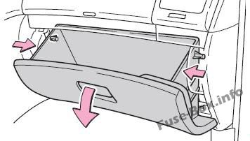
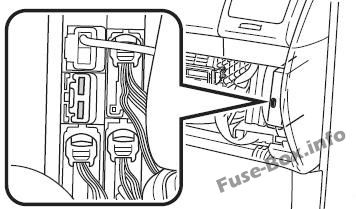
The fuse box is located in the passenger’s side of the instrument panel.
Open the glove box, slide off the damper, push in each side of the glove box to disconnect the claws.
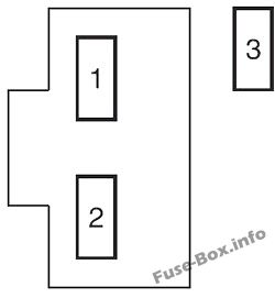
| № | Name | Ampere rating [A] | Circuit |
|---|---|---|---|
| 1 | ST | 7,5 | Multiport fuel injection system/sequential multiport fuel injection system |
| 2 | A/C | 7,5 | Manual air conditioning system |
| 3 | SFT | 5 | Shift lock control system |
Engine Compartment Fuse Box
Engine Compartment Fuse Box
Fuse box location
It is located in the engine compartment (left-side).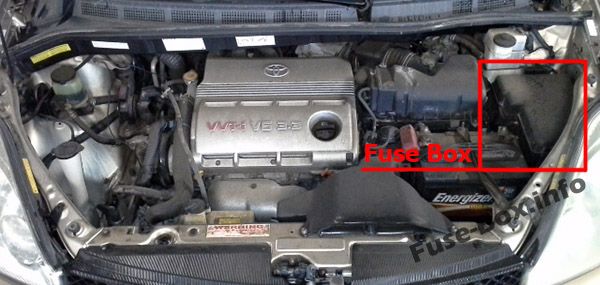
Fuse box diagram
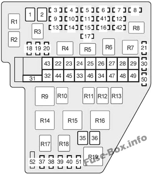
Advertisements
Assignment of the fuses and relay in the Engine Compartment
| № | Name | Amp | Protected components |
|---|---|---|---|
| 1 | MAIN | 30 | Headlights, daytime running light system, "H-LP RL" and "H-LP LL" fuses |
| 2 | AM 2 | 30 | "INJ", "IGN" and "GAUGE2" fuses |
| 3 | ETCS | 10 | Multiport fuel injection system/sequential multiport fuel injection system |
| 4 | DRL | 20 | Daytime running light system, "H-LP RH" and "H-LP LH" fuses |
| 5 | DOOR NO.2 | 25 | Power door lock system |
| 6 | HORN | 10 | Horns |
| 7 | DOME | 10 | Personal/interior lights, vanity lights, door courtesy lights, luggage compartment light, engine switch light, multi-information display |
| 8 | RAD NO.1 | 20 | 2003-2006: Audio system, navigation system |
| 8 | RAD NO.1 | 15 | 2007-2010: Audio system |
| 9 | EFI NO.1 | 20 | Multiport fuel injection system/sequential multiport fuel injection system, "EFI NO.2" fuse |
| 10 | ALT-S | 7.5 | Charging system |
| 11 | HAZ | 15 | Turn signal lights, emergency flashers |
| 12 | ECU-B | 10 | Power sliding door, air conditioning system, power windows, multiplex communication system, meter and gauge, wireless remote control system |
| 13 | H-LP RL | 15 | Right-hand headlight (low beam) |
| 13 | H-LP RH | 15 | Right-hand headlight |
| 14 | H-LP LL | 15 | Left-hand headlight (low beam), front fog lights |
| 14 | H-LP LH | 15 | Left-hand headlight |
| 15 | RAD NO.3 | 30 | Audio system |
| 16 | EFI NO.2 | 10 | Multiport fuel injection system/sequential multiport fuel injection system |
| 17 | A/F | 25 | A/F sensor |
| 18 | SPARE | 15 | Spare fuse |
| 19 | SPARE | 20 | Spare fuse |
| 20 | SPARE | 30 | Spare fuse |
| 21 | SPARE | 30 | Spare fuse |
| 22 | RR2 SEAT | 50 | Power third seat |
| 23 | HTR | 50 | Air conditioning system, "A/C" fuse |
| 24 | FAN | 50 | Electric cooling fans |
| 25 | PBD | 30 | Power back door |
| 26 | R-PSD | 30 | Right side power sliding door |
| 27 | L-PSD | 30 | Left side power sliding door |
| 28 | RR A/C | 40 | Rear air conditioning system |
| 29 | DEF | 40 | Rear window defogger, "MIR HTR" fuse |
| 30 | SPARE | 7.5 | Spare fuse |
| 31 | ALT | 140 | Charging system, "RR A/C", "HTR", "FAN", "PBD", "R-PSD", "L-PSD" and "DEF" fuses |
| 32 | ABS1 | 50 | Anti-lock brake system, traction control system, vehicle stability control system |
| 33 | ABS2 | 30 | Anti-lock brake system, traction control system, vehicle stability control system |
| 34 | ST | 30 | Starting system |
| 35 | L-RR2 SEAT | 30 | Power third seat |
| 36 | R-RR2 SEAT | 30 | Power third seat |
| 37 | H-LP RH | 10 | Right-hand headlight |
| 37 | H-LP RL | 10 | Right-hand headlight (low beam) |
| 38 | H-LP LH | 10 | Left-hand headlight |
| 38 | H-LP LL | 10 | Left-hand headlight (low beam), front fog lights |
| 39 | RSE | 7.5 | Rear seat entertainment system |
| 40 | INJ | 10 | 2007-2010: Multiport fuel injection system/ sequential multiport fuel injection system |
| 41 | - | - | Short Pin |
| 42 | - | - | - |
| 43 | - | - | - |
| 44 | - | - | - |
| 45 | - | - | - |
| 46 | - | - | - |
| 47 | - | - | - |
| 48 | - | - | - |
| 49 | - | - | - |
| 50 | - | - | - |
| 51 | - | - | - |
| 52 | - | - | Short Pin |
| Relay | |||
| R1 | Stop lights (BRK) | ||
| R2 | Air fuel ratio sensor (A/F) | ||
| R3 | Circuit opening (C/OPN) | ||
| R4 | Headlight (HEAD) | ||
| R5 | EFI | ||
| R6 | Short Pin | ||
| R7 | Rear windshield defogger (DEFOG) | ||
| R8 | Horn | ||
| R9 | Vehicle stability control (VSC MTR) | ||
| R10 | Vehicle stability control (VSC FAIL) | ||
| R11 | Daytime running light (DRL NO.4) | ||
| R12 | Daytime running light (DRL NO.2) | ||
| R13 | Daytime running light (DRL NO.3) | ||
| R14 | Electric cooling fan (FAN) | ||
| R15 | Rear air conditioning system (RR A/C) | ||
| R16 | Heater (HTR) (manual A/C) Short Pin (automatic A/C) | ||
| R17 | Starter (ST) | ||
| R18 | Air conditioner compressor clutch (MG CLT) | ||
| R19 | - |
Advertisements